
Renesas RH850 Attacks (Part 4 of 7) – Evaluation of the Fault Protection on the RH850
May 30th, 2025 by Brian
Background
In the previous blog post, we looked into the possibility of fault injecting the RH850. In this blog post, we will try to get familiar with fault injection on the RH850 by trying to glitch a few relatively simple programs. These would allow us to determine how faultable the RH850 is with the equipment we have. Work conducted by Ibrahima Keita.
Test Scenario 1
Program
Our program did the following sequence:
- Sets pin
10_9high. - Turns on the right LED (
10_10). - Checked if
xwas not equal to 100; if it wasn’t, it would turn on the left LED (10_11), and set GPIO pin10_8high. - Sets pin
10_9low.
We toggle 10_9 between high and low to easily monitor the execution state of the program, as it provides a trigger source. We want this to determine the time interval where we should perform our glitch.
The C code for this program can be found below.
/* Notes on Development board
 * Pins 10_9 - 10_6 have been broken out as standard GPIOs
 * Pin 10_10 is the right LED
 * Pin 10_11 is the left LERS
*/
int x = 100;
while (1) {
    R_PORT_SetGpioOutput(Port10, 9, High);
    R_PORT_SetGpioOutput(Port10, 10, High);
    if (x != 100) {
        R_PORT_SetGpioOutput(Port10, 8, High);
        R_PORT_SetGpioOutput(Port10, 11, High);
        countdown(500000);
    }
    R_PORT_SetGpioOutput(Port10, 9, Low);
}
Glitching Setup & Attempts
The first thing we did was identify the period between the trigger being toggled between high and low. This was done by monitoring the voltage of 10_9 with our Siglent SDS1104X-E oscilloscope, as the voltage would directly correlate to the status of the pin (HIGH being 3.3V, and LOW being 0V).
We specifically looked for a point in the graph where the pin was set HIGH, then LOW, and then brought back HIGH again, as this would represent one execution cycle of the loop. Finding the period between the two HIGH pulses gives us our glitch window, or the range of time we have to perform our fault injection. The calculated time period of our window was 20 microseconds.
Once we got this, we were able to calculate the number of cycles with some simple math. Our RH850 processor runs at 16 MHz, or 16,000,000 cycles per second. As such:
( 16,000,000 cycles1 second ) × 20 microseconds = 600 cycles
This allows us to determine the exact number of cycles our window takes relative to the clock speed of the RH850, making it easy to determine a range for our ext_offset, or how many cycles to wait after detecting the trigger to start our glitch. Furthermore, we also need to specify the range for our repeat, which is the number of pulses to generate/the amount of cycles to glitch.
We settled on the following parameters through experimentation:
ext_offsetrange [0,600].triesrange [1,30].repeatrange [10,30].
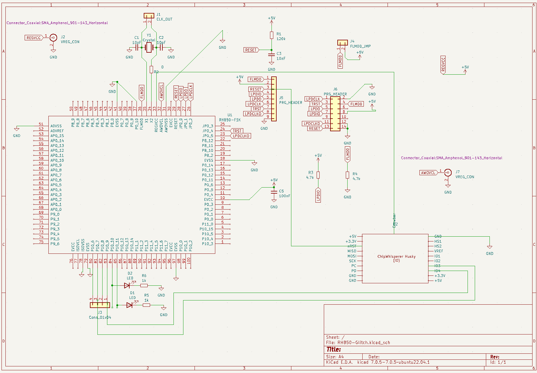
From there, we set up the ChipWhisperer to connect to the RH850 in the following way:

The Python code which sets our parameters is as follows:
gc.set_step("ext_offset", 5)
gc.set_range("ext_offset", 0, 600)
gc.set_range("repeat", 10, 30)
gc.set_range('tries', 0, 30)
However, there were no successes recorded with this process. At first, we did have an issue where the triggering was not properly detected, but even after fixing this, we did not corrupt the check.
From there, we attempted to raise the number of attempts, or tries, as this is a fairly nondeterministic process with low chances of iterative success. This did not work either. That’s when we decided to look further into it.
Problems
While this program looks relatively simple, glitching the check here is not. Below is a disassembly of the aforementioned code, generated by the disassembler IDA Pro. The green block of instructions is what we want to execute, whereas the purple blocks of instructions represent the current code execution path.
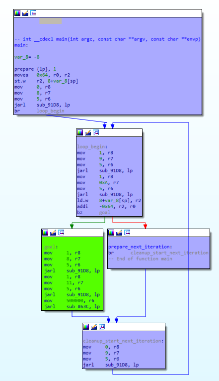
The comparison operation happens with the addi -0x64, r2, r0 instruction. We add -100 to the value stored in R2, 100. If this operation is nonzero, then the processor status word register is set to indicate this, and the conditional branch bz goal is taken, forcing our program to execute the green block of code.
The problem here is that these two instructions take up a very small amount of execution time, leaving us with an extremely tight window. Furthermore, while the timing on the trigger gives us a decent range of cycles to work with, it is still very infeasible. Operations such as adding an immediate value, and conditionally branching on a flag being set, do not account for most of the execution time of this program. The execution is dominated by the calls to R_PORT_SetGpioOutput, as those are functions which do work on the hardware. But, even then, there is only one call to that in the execution path, which would account for a significant portion of the runtime.
As such, we tried a simpler program.
Test Scenario 2
Program
This program has a very simplistic execution path compared to the first one.
- Set all GPIO pins to low.
- Set
10_9high, to use as one end of our trigger. - Read a value from the interrupt vector table (located at
0x0in the memory). - Set
10_8high, to use as the other end of our trigger. - If the value we read matches the target value (
0x831802E0), turn on the left LED (10_11).- Delay.
- Otherwise, turn on the right LED (
10_10) and set GPIO pin10_7high, so we can inform the ChipWhisperer.- Delay.
Similar to last time, we use 10_9 as a trigger point for the ChipWhisperer. But, we also use 10_8 to determine the end of the flash read, which gives us an interval for corruption with the ChipWhisperer.
The C code for this program can be found below.
/* Notes on Development board
 * Pins 10_9 - 10_6 have been broken out as standard GPIOs
 * Pin 10_10 is the right LED
 * Pin 10_11 is the left LERS
 */
int main(void) {
 // Pull all Initial GPIOs low, as to avoid false triggering
 R_PORT_SetGpioOutput(Port10, 11, Low);
 R_PORT_SetGpioOutput(Port10, 10, Low);
 R_PORT_SetGpioOutput(Port10, 9, Low);
 R_PORT_SetGpioOutput(Port10, 8, Low);
 R_PORT_SetGpioOutput(Port10, 7, Low);

 unsigned int TARGET_VAL = 0x831802E0;
 unsigned int flash_val = 0;
 // Trigger
 R_PORT_SetGpioOutput(Port10, 9, High);
 flash_val = *(unsigned int *)0x0;
 // Secondary trigger - use this to determine how long a flash read takes
 R_PORT_SetGpioOutput(Port10, 8, High);
 if (flash_val != TARGET_VAL) {
  // Turn on LED and CW know that an improper value has been read
  R_PORT_SetGpioOutput(Port10, 7, High);
  R_PORT_SetGpioOutput(Port10, 10, High);
  countdown(500000);
 }
 else if (flash_val == TARGET_VAL) {
  R_PORT_SetGpioOutput(Port10, 11, High);
  countdown(500000);
 }

 return 0;
}
Glitching Setup & Attempts
Similar to the last scenario, we identified the period between the trigger being toggled between high and low. This gave us our glitch window, or the time range where we should perform our fault injection. The calculated time period was
282828 microseconds.
Once we got this, we were able to calculate the number of cycles with some simple math. Our processor runs at 16 MHz, or 16,000,000 cycles per second. As such, the following holds true:
( 16,000,000 cycles1 second ) × 30 microseconds = 900 cycles
We can now determine a range for our ext_offset, or how many cycles to wait after detecting the trigger to start our glitch. Furthermore, we also need to specify the range for our repeat, which is the number of pulses to generate/the amount of cycles to glitch.
We settled on the following parameters initally, and converged them as needed:
ext_offsetrange [0,2800].triesrange [1,15].repeatrange [10,30].
From there, we set up the ChipWhisperer to connect to the RH850 in the following way:
Attempts, Successes(?), Failures, Success
We first decided to run our code with these parameters.
gc.set_range("ext_offset", 0, 2800)
gc.set_range('tries', 1, 15)
gc.set_range("repeat", 10, 30)
We had a success within a few minutes (and of course, I didn’t see it happen, since I turned away to grab water at just the right time)!
Success! -- ext_offset = 1475, width = 40, repeat = 10I was skeptical, so we ran the code again. This time, I got just these successes:
Success! -- ext_offset = 0, width = 40, repeat = 10
Success! -- ext_offset = 2, width = 40, repeat = 10
Success! -- ext_offset = 3, width = 40, repeat = 10
At this point, I was very confused. And I didn’t have any oscilloscope instrumentation to capture the images on successes (which made this even funnier). So, I decided to run comprehensive tests on that range.
I then, naively, ran the code with the following parameters:
gc.set_range("ext_offset", 1450, 1490)
gc.set_range('tries', 1, 15)
gc.set_range("repeat", 20, 20)
While I do not have the exact run captured (since this was right before my instrumentation implementation), the following image collage is from a similar run with mostly the same parameters.
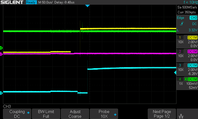
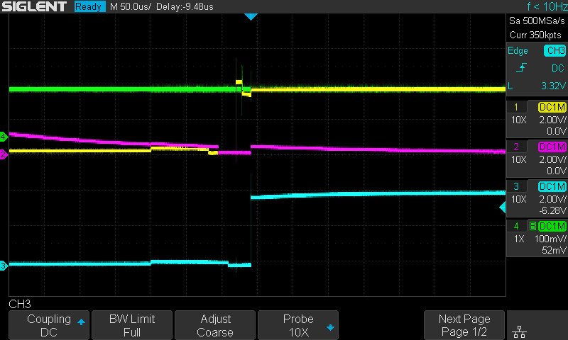
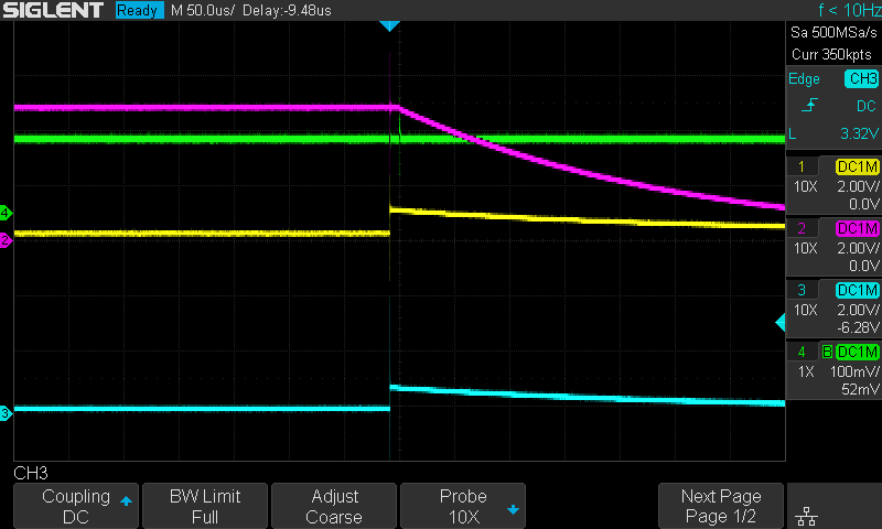
In each of the images:
- The green line represents the crowbar/regulator voltage.
- The yellow and pink lines represent the voltages on
10_9and10_8after they are set to high/low, and the blue line represents the voltage on10_10. This gives us a visual of our window. - The blue line represents the voltage on
10_10. For us to determine that our glitch was a success, this line should go fromLOW(0V) toHIGH(3.3V) and stay there (similar to the pink line), as this would mean we managed to corrupt the memory check. This means that if there is no change on the blue line’s voltage, we did not hit the glitch.
As shown in the image, the blue line’s voltage did not have any significant change, meaning the glitch did not hit. So, I then attempted to sweep over a range of parameters in various ways. These are not all of the options I have tried, but just some which yielded some interesting results.
The collage below was generated with the following parameters:
gc.set_range("ext_offset", 0, 2800)
gc.set_range('tries', 1, 2)
gc.set_range("repeat", 10, 30)
gc.set_global_step(10)
The collage below was generated with the following parameters:
gc.set_range("ext_offset", 0, 2800)
gc.set_range('tries', 1, 2)
gc.set_range("repeat", 10, 10)
gc.set_global_step(10)
The collage below was generated with the following parameters:
gc.set_range("ext_offset", 0, 2800)
gc.set_range('tries', 1, 10)
gc.set_range("repeat", 10, 10)
gc.set_global_step(10)
Unfortunately, this did not give us any successes, no matter how many iterations of this test I ran. I did learn quite a few things from these runs, though.
- Most, if not all
ext_offsetvalues under 1300 definitely crash the processor, or result in no changes. - A
repeatrange of [10,30] definitely yields some decent results, but not always consistently. - Capturing the oscilloscope image every single iteration of our glitch bottlenecks our glitching process significantly.
I decided to run the following comprehensive test over the weekend (3 days), because our time interval can be slightly larger or shorter depending on various conditions which are out of our control. For this, I disabled the oscilloscope instrumentation, as it caused crashes in the middle of the glitching (and I did not want that to happen over the weekend)!
gc.set_range("ext_offset", 1300, 2800)
gc.set_range('tries', 1, 15)
gc.set_range("repeat", 20, 20)
gc.set_global_step(0.1)
gc.set_step('tries', 1)
When I came back after 3 days, it was still running (somehow), but I noticed the following messages, which told me pretty much all I needed to know.
Success! -- ext_offset = 1317, width = 40, repeat = 10
Success! -- ext_offset = 1343, width = 40, repeat = 10
Success! -- ext_offset = 1609, width = 40, repeat = 10
Success! -- ext_offset = 1737, width = 40, repeat = 10
Success! -- ext_offset = 1739, width = 40, repeat = 10
Success! -- ext_offset = 1742, width = 40, repeat = 10
The latter 3 ext_offset values tell a story. 1737, 1739, and 1742 are all very close together, while 1317, 1343, and 1609 are a bit further away. As such, I decided to run some tests on the range [1737,1742].
What I ended up doing was simple. First, I edited the script to have the following parameters:
gc.set_global_step(1)
gc.set_range("ext_offset", 1720, 1742)
gc.set_range('tries', 0, 15)
gc.set_range("repeat", 10, 11)
gc.set_step('tries', 1)
 gc.set_step('repeat', 0.1)
Then, I changed the loop in our notebook, particularly at the comment # Should not touch this unless you know what the deal is, to run infinitely:
while True:
    for glitch_setting in gc.glitch_values():
        chipwhisperer.glitch.ext_offset = glitch_setting[0]
        chipwhisperer.glitch.repeat = glitch_setting[2]
        reboot_flush()
        chipwhisperer.io.glitch_hp = False
        chipwhisperer.io.glitch_hp = True
        chipwhisperer.io.glitch_lp = False
        chipwhisperer.io.glitch_lp = True
        if chipwhisperer.io.tio_states[2] == 1:
            gc.add("done", (chipwhisperer.glitch.ext_offset, glitch_setting[1], chipwhisperer.glitch.repeat))
            print("Success! -- offset = {}, width = {}, ext_offset = {}, repeat = {}".format(chipwhisperer.glitch.offset, chipwhisperer.glitch.width, chipwhisperer.glitch.ext_offset, chipwhisperer.glitch.repeat))
        else:
            gc.add("reset", (chipwhisperer.glitch.ext_offset, glitch_setting[1], chipwhisperer.glitch.repeat)) print("Done glitching")
After a few runs, I saw consistent results:
Done glitching
[many more of the above]
Success! -- ext_offset = 1732, width = 40, repeat = 10
Success! -- ext_offset = 1739, width = 40, repeat = 10
Done glitching
[many more of the above]
Success! -- ext_offset = 1735, width = 40, repeat = 10
Done glitching
[many more of the above]
Success! -- ext_offset = 1740, width = 40, repeat = 10
Done glitching
[many more of the above]
Success! -- ext_offset = 1731, width = 40, repeat = 10
Done glitching
[many more of the above]
Success! -- ext_offset = 1738, width = 40, repeat = 10
Done glitching
[many more of the above]
Success! -- ext_offset = 1737, width = 40, repeat = 10
Done glitching
[many more of the above]
Success! -- ext_offset = 1733, width = 40, repeat = 10
Done glitching
[many more of the above]
To supplement these, the oscilloscope was reconfigured to trigger only when the pin we wanted to go high did so. This, along with my instrumentation, allowed us to capture some detailed photos of the waveforms, which confirmed these were not flukes!
And, just for fun, I ran the above code overnight and came back to the following output:
Success! -- ext_offset = 1740, width = 40, repeat = 10
Success! -- ext_offset = 1732, width = 40, repeat = 10
[143 successes later...]
Success! -- ext_offset = 1737, width = 40, repeat = 10
Success! -- ext_offset = 1739, width = 40, repeat = 10
Success! -- ext_offset = 1730, width = 40, repeat = 10
Success! -- ext_offset = 1740, width = 40, repeat = 10
Success! -- ext_offset = 1732, width = 40, repeat = 10
Success! -- ext_offset = 1741, width = 40, repeat = 10
As a result of our testing, we can reasonably conclude that, with our setup, using an ext_offset range of [1730,1741] with a repeat range of [10,11] yielded many successful check bypasses in this testing scenario.
That being said, we have shown that the RH850 is susceptible to fault injection attacks. Now, it’s time to take it one step further. In the next blog post, we will attempt to tackle the serial programming ability.