
Set-Top Box RE: 6-part series (2 of 6)
August 27th, 2024 by Brian
The following is part 2 of a 6-part series detailing the examination of the security of Set-Top Boxes. The research was conducted by Om and Jack, two of our interns this past summer. Enjoy!
Blog Post 2: Hardware Teardown & Board Familiarization
Background Information
In our last post we talked about Depthcharge and ADB which are important tools we will be using throughout this blog series.
Overview
With this post we will teardown each box, look at it’s components, and figure out how we can interact with it(aside from just using HDMI).
To get started let’s take a look at each boxes availability, and do a hardware teardown to get an idea of the similarities in the components of each board.
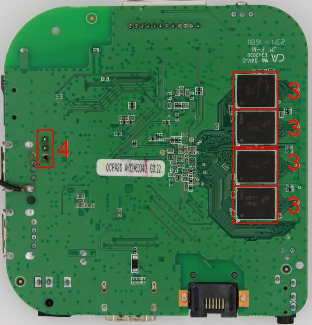
8K618-T
The first STB is the 8k618-T is available on Amazon for $37.99.

Let’s tear it down:
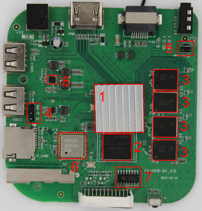
| Label | Part Number | Description | Datasheet |
|---|---|---|---|
| 1 | Allwinner H616 | CPU | User manual |
| 2 | SKhynx H26M642O8EMR e-NAND 616A | 32GB eMMC | Datasheet |
| 3 | 3ME77 D9PQL | DDR3 SDRAM MT41K1G4RH-125 | Datasheet |
| 4 | NA | 3 Pin UART Header | NA |
| 5 | NA | UBoot / Rec Switch (used to enter FEL mode) | NA |
| 6 | HK6334Q | WiFi SDIO Chip | Not found |
| 7 | FD65OB CQCBROAB21 | LED drive control | Datasheet |
| 8 | AXP313A P3017AA | Power management | Possible datasheet |
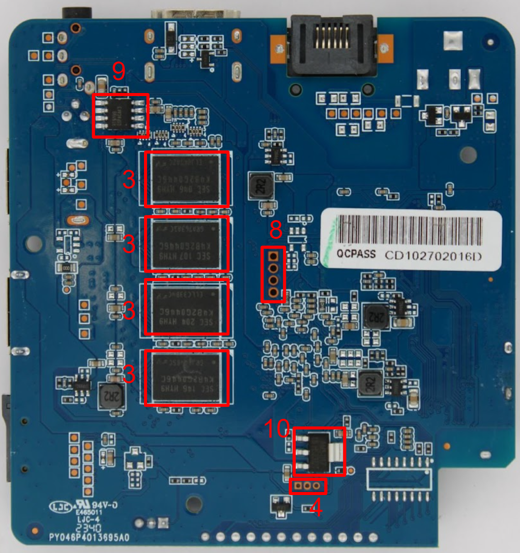
H96 MAX
The second STB is the H96 it is available on Amazon for $48.

Let’s tear it down:
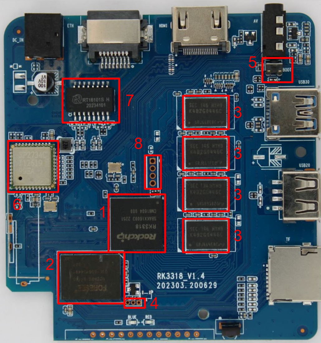
| Label | Part Number | Description | Datasheet |
|---|---|---|---|
| 1 | RK3318 | CPU | Datasheet |
| 2 | NCEMBSF9-16G | 16GB eMMC | Datasheet |
| 3 | K4B2G0446C-HYH9 | DDR3L SDRAM | Datasheet |
| 4 | NA | 3 Pin UART Header | NA |
| 5 | NA | UBoot / Rec Switch (possibly used to enter download mode?) | NA |
| 6 | SP2734C J12618 99EA | Wifi & Bluetooth | Not found |
| 7 | RT16101S | Magnetic Transformer | Not found |
| 8 | NA | 4 Pin UART Header? | NA |
| 9 | RT9199 | 2A Peak Sink/Source Bus Termination Regulator | datasheet |
| 10 | AMS1117 | 1A LOW DROPOUT VOLTAGE REGULATOR | datasheet |
Rupa 8K
The third STB is the Rupa8k which can be found on Amazon for $24.99.

Let’s tear it down:
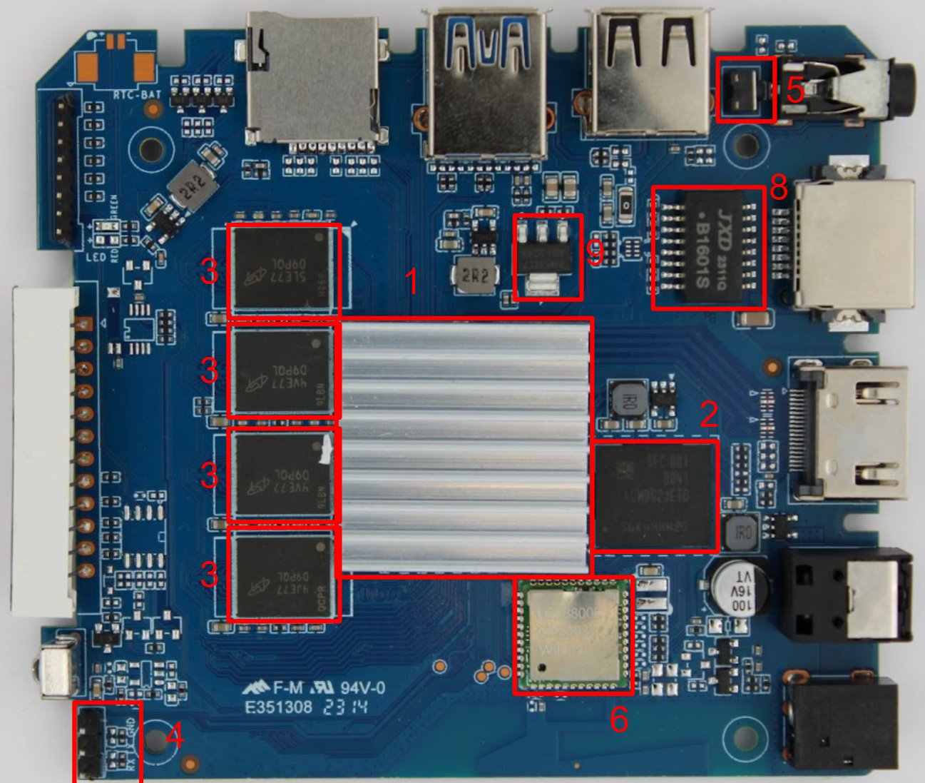
| Label | Part Number | Description | Datasheet |
|---|---|---|---|
| 1 | Rockchip RK3528 | quad-core 64-bit CPU | Datasheet |
| 2 | KLM8G1GETF-B041 | eMMC | Datasheet |
| 3 | MT41K1G4RH-125:E | SDRAM – DDR3 4Gbit Parallel 800 MHz 13.75 ns | Datasheet |
| 4 | NA | 3 Pin UART Header | NA |
| 5 | NA | UBoot / Rec Switch (possibly used to enter download mode?) | NA |
| 6 | LGX8800D CN2303Y | Wifi 6 | Not found |
| 7 | AIP1628 | LED Driver | Datasheet |
| 8 | B1601S | RJ45 Transformer ROHS | Datasheet |
| 9 | AMS1117 | 1A LOW DROPOUT VOLTAGE REGULATOR | Datasheet |
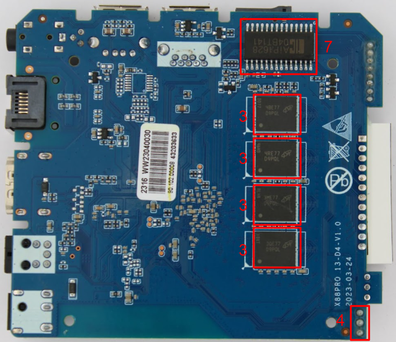
X88 Pro 10
The fourth STB is the X88 Pro 10 which can be found on Amazon for $26.97.

Let’s tear it down:
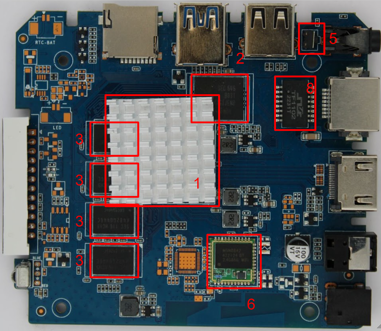
| Label | Part Number | Description | Datasheet |
|---|---|---|---|
| 1 | Rockchip RK3318 | Quad-core 64-bit Cortex-A53 CPU & GPU | Datasheet |
| 2 | KLMAG1JENB-B031 | 16 GB eMMC Flash | Similar datasheet |
| 3 | K4B2G0446C-HCH9 | DDR3 SDRAM 2Gbit 512Mx4 1.5V | Datasheet |
| 4 | NA | 3 Pin UART Header | NA |
| 5 | NA | UBoot / Rec Switch (possibly used to enter download mode?) | NA |
| 6 | MSN8842 | WiFi & Bluetooth | Not found |
| 7 | AIP1628 | LED Driver | Datasheet |
| 8 | TF1102MG | 10/100BASE-Tx Magnetics Module | Datasheet |
TSHDMX10
The fifth STB is the TSHDMX10 which can be found on Amazon for $29.99.
Let’s tear it down:
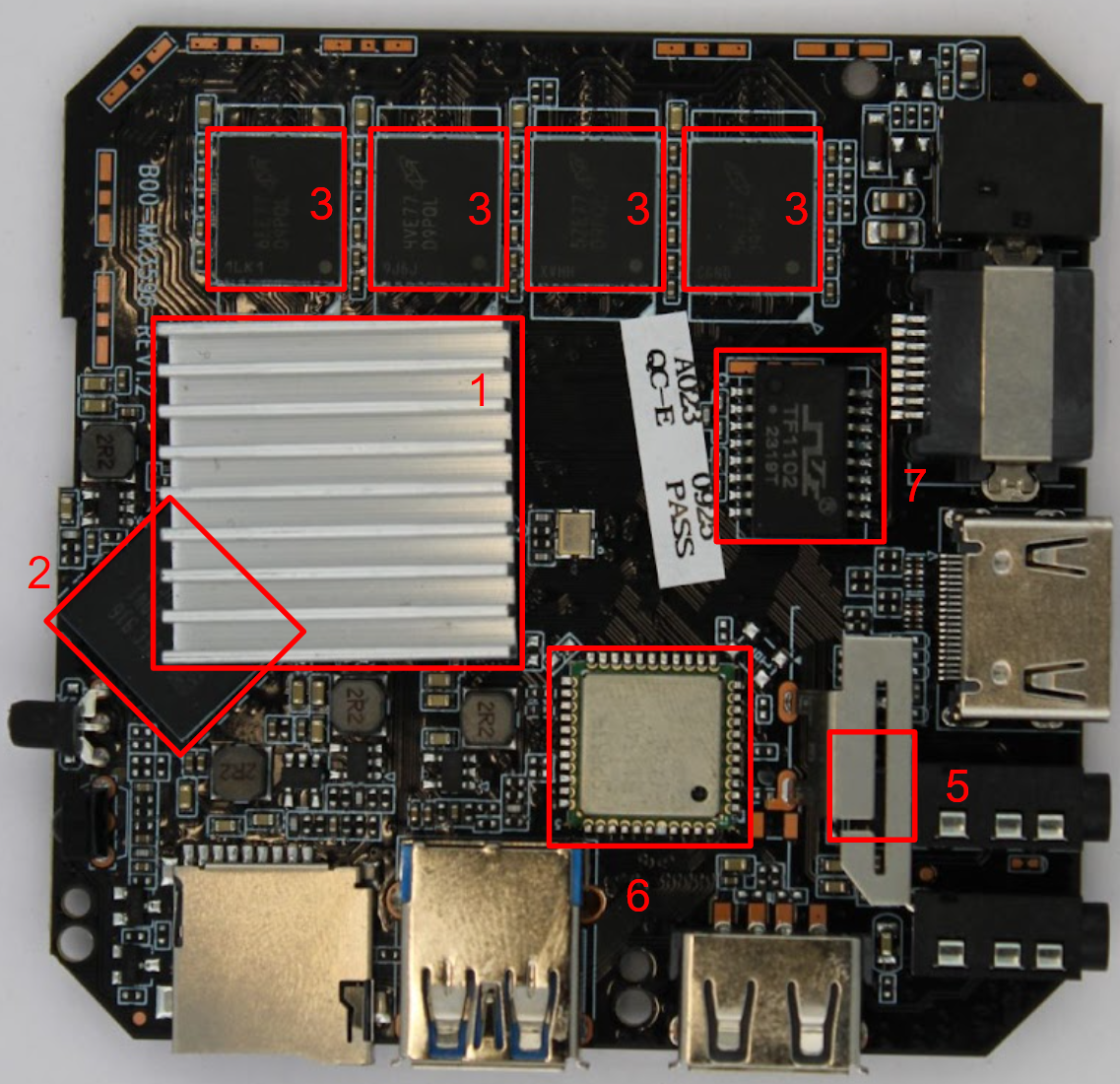
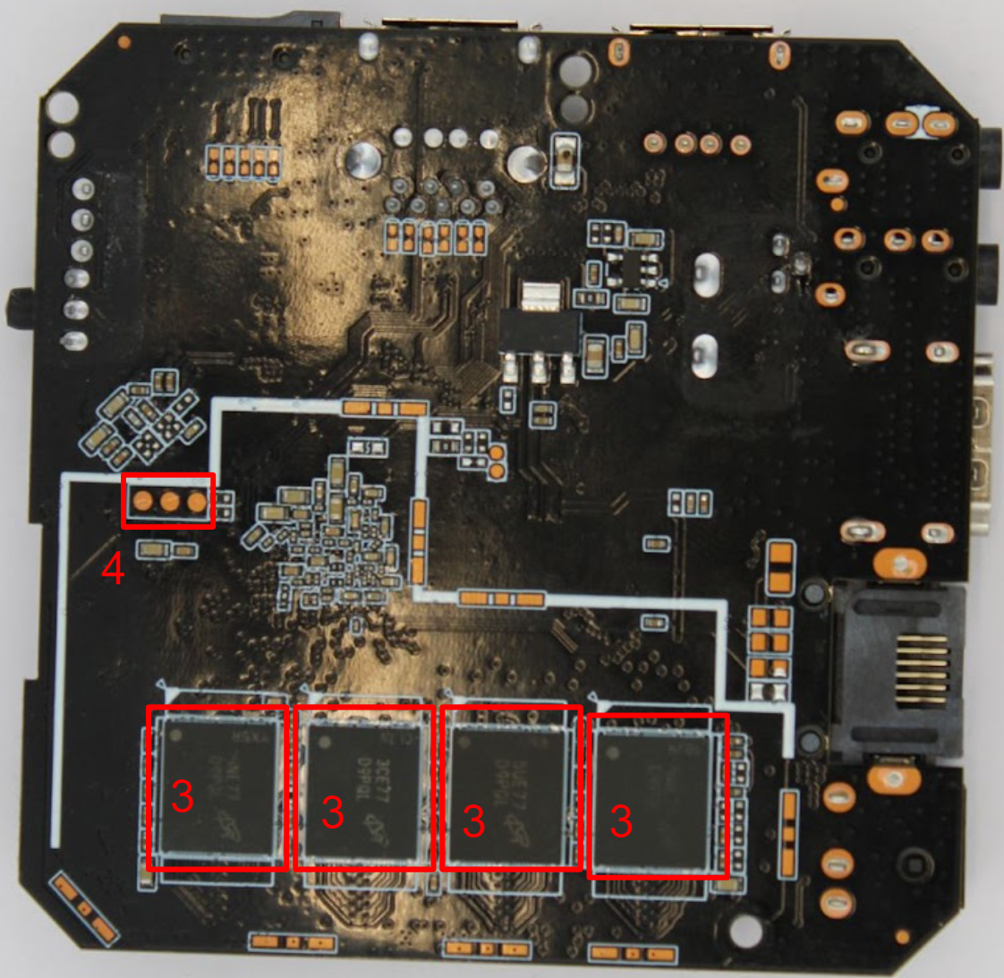
| Label | Part Number | Description | Datasheet |
|---|---|---|---|
| 1 | Rockchip RK3528 | CPU & GPU | Datasheet |
| 2 | KM3V6001CM-B041 | 64Gb eMMC flash | Not found |
| 3 | MT41K1G4RH-125:E | SDRAM – DDR3 4Gbit Parallel 800 MHz 13.75 ns | Datasheet |
| 4 | NA | 3 Pin UART Header | NA |
| 5 | NA | UBoot / Rec Switch (possibly used to enter download mode?) | NA |
| 6 | RTL8822CS | 802.11 WiFi & Bluetooth | Datasheet |
| 7 | TF1102MG | 10/100BASE-Tx Magnetics Module | Datasheet |
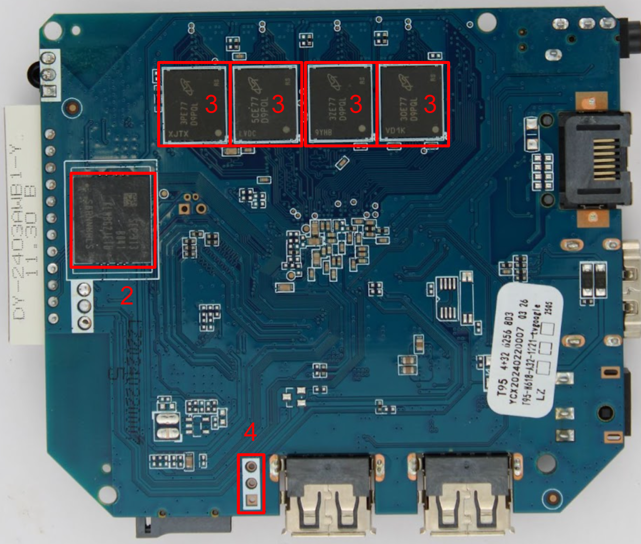
T95 – TT TV Box
The sixth and final STB we will look at is the T95 which can be found on Amazon for $29.99.
Let’s tear it down:
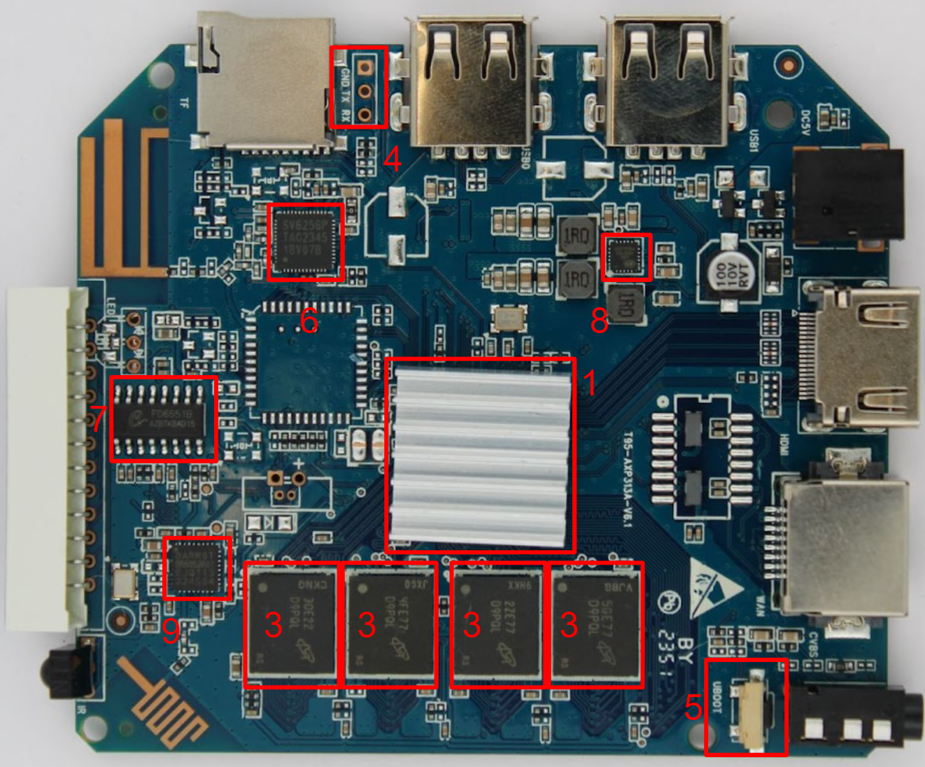
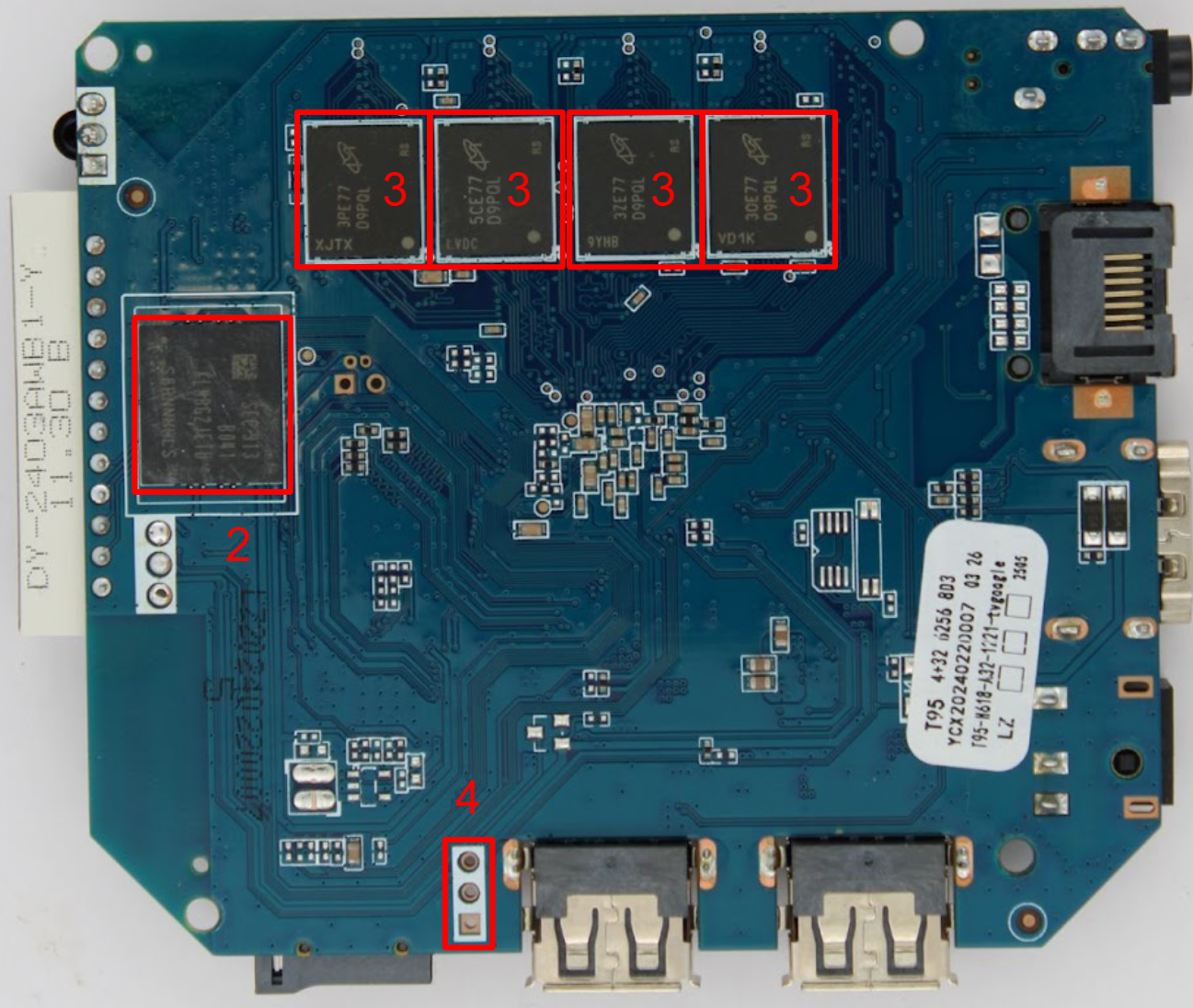
| Label | Part Number | Description | Datasheet |
|---|---|---|---|
| 1 | Allwinner H616 | CPU | User manual |
| 2 | KLM8G1GETF-B041 | 32 GB eMMC | Datasheet |
| 3 | K4B2G0446C-HCH9 | DDR3 SDRAM 2Gbit 512Mx4 1.5V | Datasheet |
| 4 | NA | 3 Pin UART Header | NA |
| 5 | NA | UBoot / Rec Switch (used to enter FEL mode) | NA |
| 6 | SV6256P | WiFi chip | Datasheet |
| 7 | FD6551B | TV remote controller IC programmer? | Not found |
| 8 | AXP313A | Integrated Power Management | Datasheet |
| 9 | BARROT BR8052A01 | Bluetooth | Datasheet |
Interaction
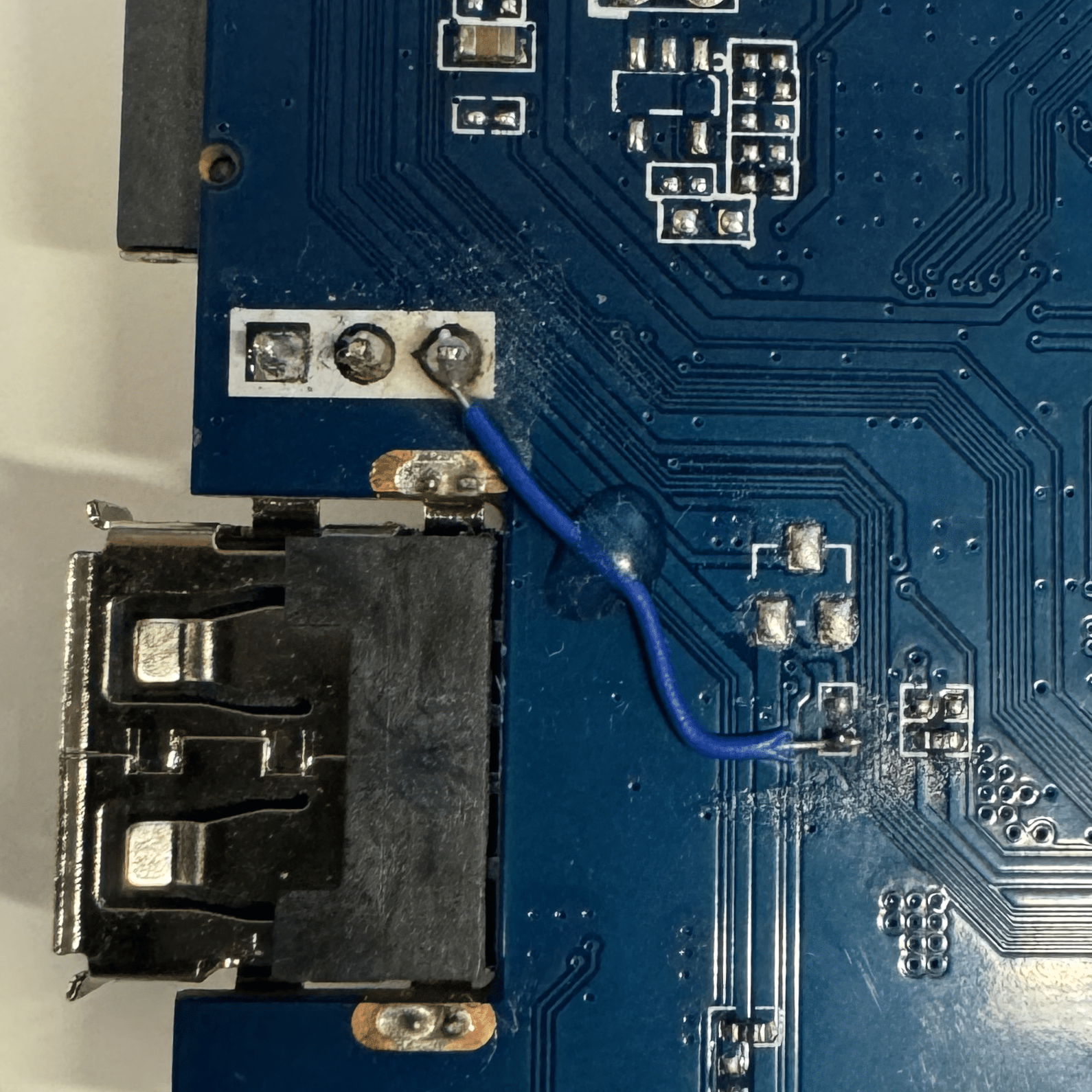
From the pictures we have UART connects labeled number 4 on all of the boards. To make them easier to access we wired headers to the thru-holes or wires to the pads.
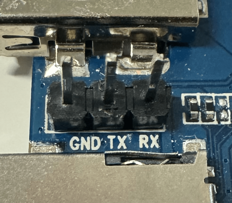
To confirm this we confirmed the ground using a multimeter in continuity mode with one probe in the ground via and the other probe on a known ground such as the USB housing. We also confirmed that it transmitted (via TX) by switching the multimeter to DC voltage mode, dropping the positive probe into the TX via, and the ground probe into the ground via. After power cycling the device we see the voltage pulled up to 3.3V and then drop sharply and come back up. This confirms that this is a UART transmit via because those voltage drops are data being sent over the line. This also gives us a logic level of 3.3V which is to be expected with a device like this, but it is still a good thing to confirm.
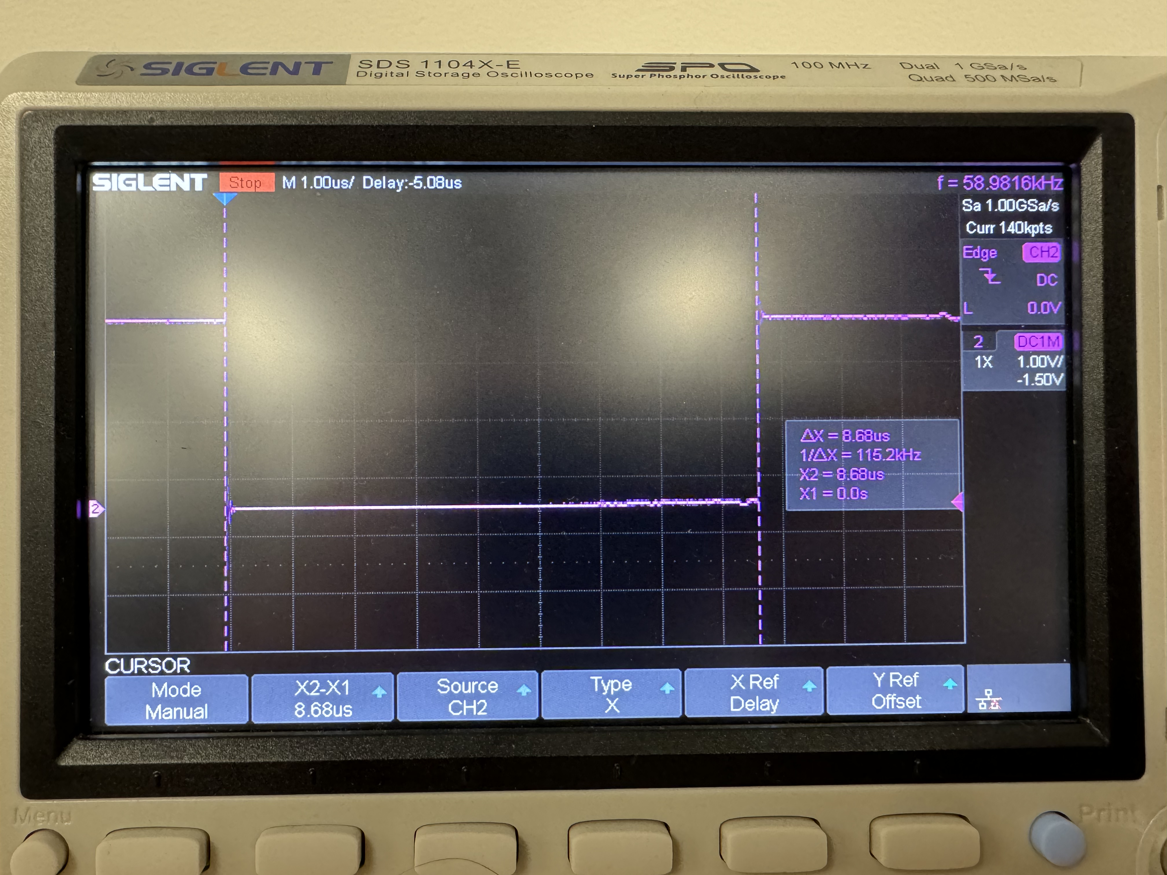
Our next step is to further analyze the debug headers with an oscilloscope. The oscilloscope that we are using is the Siglent 1104X-E. Like the multimeter, we attach the positive probe to the TX and the ground probe to the ground. Unlike the multimeter, the oscilloscope will give us a capture of the voltage over time. Then we will set a good scale and set a normal trigger that will trigger on a falling edge. A capture should look like this:
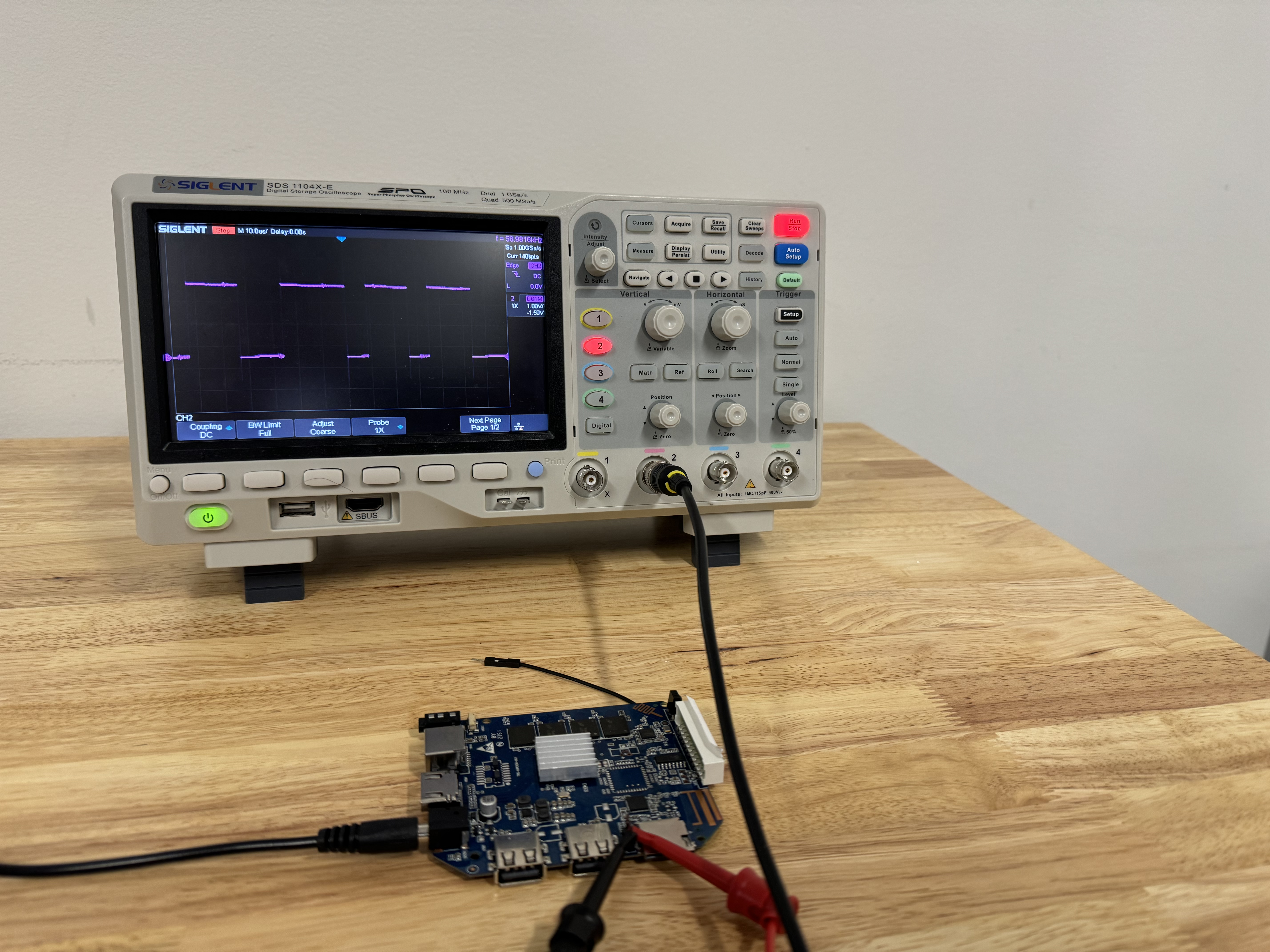
The capture is clear and we can see the 1s and 0s that UART will convert to data. We will find the smallest piece of data and zoom in on it. Then we want to use the cursor function on the oscilloscope to calculate the baud rate which is 1/△x. In this case, it is 115.2 kHz.
With this baud rate, we can now understand the serial port. To interface with the console we will wire up an FTDI serial to USB adapter to the UART headers. Then we can run the screen command:
sudo screen -L -Logfile <logfile> <USB device> <baud rate>
This will drop us to a terminal, emulating what we see on the boot of the box. After power cycling the box, we get the following output on the T95 for example:
[331]HELLO! SBOOT is starting!
[334]sboot commit : 749c1f9a
[337]set pll start
[340]periph0 has been enabled
[343]set pll end
[344]unknow PMU
[346]unknow PMU
[348]tPMU: 0x9c
[350]PMU: AXP1530
[352]dram return write ok
[354]board init ok
[356]try to probe rtc region
[359]DRAM BOOT DRIVE INFO: V0.651
[362]the chip id is 0x5000
[365]chip id check OK
[369]DRAM_VCC set to 1500 mv
[372]DRAM CLK =600 MHZ
[374]DRAM Type =3 (3:DDR3,4:DDR4,7:LPDDR3,8:LPDDR4)
[382]Actual DRAM SIZE =4096 M
[385]DRAM SIZE =4096 MBytes, para1 = 310b, para2 = 10000000, dram_tpr13 = 6041
[394]DRAM simple test OK.
[396]rtc standby flag is 0x0, super standby flag is 0x0
[402][mmc]: mmc driver ver 2021-10-12 13:56
[406][mmc]: b mmc 2 bias 0
[414][mmc]: Wrong media type 0x0, but host sdc2, try mmc first
[420][mmc]: ***Try MMC card 2***
[575][mmc]: RMCA OK!
[577][mmc]: wrong freq 2 at spd md 2
[581][mmc]: MMC 5.1
[583][mmc]: HSSDR52/SDR25 8 bit
[586][mmc]: 50000000 Hz
[589][mmc]: 29820 MB
[591][mmc]: ***SD/MMC 2 init OK!!!***
[679]read toc1 from emmc 32800 sector
[683]OLD version: 0.0
[685]NEW version: 0.0
[761]load rotpk hash
[824]load monitor-key hash
[827]load monitor hash
[1031]load boot-key hash
[1034]load boot hash
[1100]load vbmeta-key hash
[1103]load vbmeta hash
[1170]load recovery-key hash
[1173]load recovery hash
[1176]monitor entry=0x48000000
[1179]uboot entry=0x4a000000
[1182]optee entry=0x48600000
[1185]tunning data addr:0x4a0003e8
[1191]run out of boot0
NOTICE:  BL3-1: v1.0(debug):05d6c57
NOTICE:  BL3-1: Built : 13:35:35, 2021-10-28
NOTICE:  BL3-1 commit: 8
NOTICE:  cpuidle init version V1.0
NOTICE:  secure os exist
MESSAGE: [0x0] TEE-CORE: OP-TEE version: 5c40397e #1 Tue Feb  2 07:45:37 UTC 2021 arm
NOTICE:  BL3-1: Preparing for EL3 exit to normal world
NOTICE:  BL3-1: Next image address = 0x4a000000
NOTICE:  BL3-1: Next image spsr = 0x1d3


U-Boot 2018.05-g23fdfbb-dirty (Mar 19 2024 - 12:08:10 +0800) Allwinner Technology

[01.284]CPU:   Allwinner Family
[01.287]Model: sun50iw9
I2C:   ready
[01.291]DRAM:  2 GiB
[01.294]Relocation Offset is: 75ebf000
[01.337]secure enable bit: 1
[01.339]pmu_axp152_probe pmic_bus_read fail
[01.343]PMU: AXP1530
[01.349]CPU=1008 MHz,PLL6=600 Mhz,AHB=200 Mhz, APB1=100Mhz  MBus=400Mhz
[01.358]drv_disp_init
[01.389]__clk_enable: clk is null.
[01.395]drv_disp_init finish
[01.397]gic: sec monitor mode
[01.427]flash init start
[01.430]workmode = 0,storage type = 2
[01.433]MMC:     2
[01.434][mmc]: mmc driver ver uboot2018:2021-07-19 14:09:00
[01.441][mmc]: get sdc_type fail and use default host:tm4.
[01.452][mmc]: get sdc2 sdc_dis_host_caps 0x1c0.
[01.456][mmc]: SUNXI SDMMC Controller Version:0x40502
[01.617][mmc]: Best spd md: 1-HSSDR52/SDR25, freq: 2-50000000, Bus width: 8
[01.624]sunxi flash init ok
[01.628]Loading Environment from SUNXI_FLASH... OK
secure storage read hdcpkey fail
[01.641]secure storage read hdcpkey fail with:-1
secure storage read widevine fail
[01.649]secure storage read widevine fail with:-1
[01.654]usb burn from boot
delay time 0
weak:otg_phy_config
[01.667]usb prepare ok
[02.470]overtime
[02.474]do_burn_from_boot usb : no usb exist
[02.478]boot_gui_init:start
FAT: Misaligned buffer address (bbe78398)
32 bytes read in 4 ms (7.8 KiB/s)
tcon_de_attach:de=0,tcon=2[02.762]boot_gui_init:finish
[02.765]bmp_name=bootlogo.bmp
2764922 bytes read in 60 ms (43.9 MiB/s)
[02.846][mmc]: delete mmc-hs400-1_8v from dtb
[02.850][mmc]: delete mmc-hs200-1_8v from dtb
[02.854][mmc]: delete mmc-ddr-1_8v from dtb
[02.858][mmc]: get max-frequency ok 50000000 Hz
[02.872]update dts
** Unrecognized filesystem type **
[02.882]load file(ULI/factory/rootwait init.txt) error.
** Unrecognized filesystem type **
[02.896]load file(ULI/factory/snum.txt) error.
[02.900]name in map mac
** Unrecognized filesystem type **
[02.912]load file(ULI/factory/wifi_mac.txt) error.
** Unrecognized filesystem type **
[02.926]load file(ULI/factory/bt_mac.txt) error.
** Unrecognized filesystem type **
[02.939]load file(ULI/factory/selinux.txt) error.
** Unrecognized filesystem type **
[02.953]load file(ULI/factory/specialstr.txt) error.
[02.964]update part info
[02.988]update bootcmd
[02.990]No ethernet found.
Hit any key to stop autoboot:  0
[03.508]not supported key
[03.510]actual n size:1000, e:10001
[03.513]expect n size:800, e:10001
show hash of file
fb 5b c2 57 c8 0c ab 95 5f ad 65 6a a5 30 cd 18
a4 7f 72 f9 8a 5b 19 af 9a 3c 31 aa 5d 89 fe 6a

image vbmeta hash valid
CACHE: Misaligned operation at range [44ffffe0, 462a8800]
[03.691]Starting kernel ...
The only caveat to this is on the T95. While we were in the serial console, we noticed that we could not give any input via the RX line. Typically we could type on the Linux terminal that presents itself. We used a technique where we used the continuity mode on the multimeter with one probe attached to the rx pin and the other attached to the de-soldering wick which created a brush for us to use to find where rx is connected to across the board. After brushing around the CPU we found no continuity meaning that RX is not connected. However, we did find what appeared to be a missing component. Probing the other side of the component and CPU, we found that it was connected, meaning if that component was in place then RX would be able to talk to the CPU. We jumped RX to the other side of the missing component and it worked.
Conclusion
In this blog, we looked at each board, identified import components, and got a linux terminal. With that we have completed what is necessary with the hardware (for now) and we can move onto the filesystem analysis overview! Check out our next blog post for filesystem extraction!