
Set-Top Box RE: 6-part series (3 of 6)
August 28th, 2024 by Brian
The following is part 3 of a 6-part series detailing the examination of the security of Set-Top Boxes. The research was conducted by Om and Jack, two of our interns this past summer. Enjoy!
Blog Post 3: Filesystem Extraction
Background Information
In our previous post we did a teardown of each board to familiarize ourselves with the hardware and get a linux shell.
Overview
With this post we will dump the flash on each box using various methods.
Console Access
Across all of the devices we surveyed, we were able to get root-shell access through ADB. From box to box, there were slight differences, but the most “complex” it got was enabling developer mode and turning on ADB through the settings.
Here is how to do it on the T95 for example: – Enable developer settings, like any other Android device by going to Settings => Device Preferences => About and clicking the build tab 7 times. – Then enable debugging via USB by going Settings => Device Preferences => Developer Options and enable USB debugging. – Now connect a USB cable from the box to a laptop and install ADB based on your system – Type adb devices to confirm that the device is connected – Run adb root and then adb shell to have access to a root shell
All of the boxes except one had ADB over the network-enabled which can be connected to using:
adb connect <ip address>
adb root
adb remount
adb shell
Alternatively, we could also use ADB over USB. Note: ADB over USB is generally only enabled on a single USB port and will not work over the other one.
Now we have a secondary root shell into all the boxes that is super easy to interact with. We will now examine the the bootloader(s) in use and how we might be able to leverage those to easily extract the filesystem.
U-Boot: An Overview
Before we go any further it is important to get a solid understanding of what U-Boot is, without it the rest of this writeup will not make any sense.
U-Boot (Universal Boot Loader) is an open-source boot loader widely used in embedded systems. Its primary function is to initialize hardware components, load the operating system kernel (such as Linux) from a storage device into memory, and then transfer control to the OS. U-Boot is super versatile and used in all kinds of systems. It provides many commands that make low-level interaction easy. It is also relocatable meaning it changes location which will be important later.
Firmware Extraction: Rupa8k, TSHDMX10, H96, X88Pro10
Lucky for us the firmware extraction across 4 of the boards was nearly identical.
The first step for us is to drop into U-Boot. We can do this manually over UART by hitting CTRL + C to ensure we can get in. After we have confirmed that we can access U-Boot let’s automate this process so that we can get consistent logs across all the STBs:
import depthcharge
import os
import time
import serial

DEVICE = "/dev/ttyAMA0"
BAUD = 1500000
DEVICE_NAME = "test"
BLOCK_DEVICE = "sdb"

NEW_LINE_TIMEOUT = 10
BOOT_TIMEOUT = 100

dev_name_input = input(f"Device name({DEVICE_NAME}): ")
if dev_name_input:
    DEVICE_NAME = dev_name_input

try:
    os.makedirs(DEVICE_NAME)
except(FileExistsError):
    if not input(f"[WARNING] {DEVICE_NAME} already used. Are you sure you want to continue(y/N): ") == "y":
        exit(1)

baud_input = input(f'Device baud rate({BAUD}): ')
if baud_input:
    BAUD = int(baud_input)

print(f"[INFO] connecting with depthcharge on {DEVICE}:{BAUD}")
conn = depthcharge.Console(f"{DEVICE}:{BAUD}", prompt="=> ")
print("[INFO] Connected!")

context = depthcharge.Depthcharge(conn, arch="arm")
print("[INFO] Got uboot shell")
Now that we have a U-Boot shell through depthcharge let’s send some commands to get logs to reference later:
with open(f"{DEVICE_NAME}/uboot_info.txt", 'w') as log:
    # Help
    print("[INFO] Saving help data")
    help = context.send_command("help")
    log.write(f"Help:\n{help}")

    #envs
    print("[INFO] Saving enviornment variables")
    log.write(f"\n\nEnvs:\n{context.send_command('printenv')}")

    # get partitions
    print("[INFO] Saving partition data")
    partitions = context.send_command("part list mmc 0")
    log.write(f"\n\nPartitions:\n{partitions}")
    partitions = int(partitions[:partitions.rfind("attrs:")].split("\n")[-2].split("\t")[0].strip())
    print(f"[INFO] Found {partitions} partitions")

    # get ext4 list
    print("[INFO] Saving ext4 data")
    log.write(f"\n\nExt4 List(int):\n{context.send_command(f'ext2ls mmc 0:{partitions}')}")
    log.write(f"\n\nExt4 List(hex):\n{context.send_command(f'ext2ls mmc 0:{hex(partitions)}')}")
Next, let’s prepare to pull the flash by checking that the ums command is present. The UMS (Universal Mass Storage) command is used to make our U-Boot device a USB host and enable file transfers. Let’s run this command and copy the firmware off using dd.
# check for ums
if help.find("ums") == -1:
    print("[ERROR] ums not found, unable to pull flash")
    exit(1)

# pull flash
print("[INFO] Reading flash over USB")
context.send_command("ums 0 mmc 0")


block_dev_input = input(f"Block device({BLOCK_DEVICE}): ")
if block_dev_input:
    BLOCK_DEVICE = block_dev_input

for i in range(1, partitions + 1):
    os.system(f"sudo dd if='/dev/{BLOCK_DEVICE}{i}' of='{DEVICE_NAME}/partition_{i}' bs=1M status=progress")

print("[INFO] Reconnecting with pyserial")
conn.close()
conn = serial.Serial(DEVICE, BAUD)
Last let’s get the kernel logs and finish the program:
# Boot log
print("[INFO] Booting device and reading boot log")
with open(f"{DEVICE_NAME}/boot_log.txt", "w") as f:
    conn.write(b'\x03boot\n')
    boot_start_time = time.time()
    last_line_time = boot_start_time
    while True:
        line = conn.readline().decode()
        f.write(line)

        curr_time = time.time()
        if curr_time - boot_start_time > BOOT_TIMEOUT:
            print('[INFO] Boot timeout reached')
            break
        if curr_time - last_line_time > NEW_LINE_TIMEOUT:
            print('[INFO] New line timeout reached')
            break
        last_line_time = curr_time

print("[INFO] Done!")
Just like that we have dumped the firmware for 4 of our 6 STBs.
8K618-T
When booting the 8k618, it did not provide any time to stop the autoboot process. This meant we were unable to access the U-Boot shell. Because of this, we decided to live-image it instead. This meant the partitions would still be mounted while we read them. To live-image it, we first entered recovery mode using the reboot recovery command. Once in recovery mode, we were able to copy the contents of the eMMC onto a flash drive using
# Create a mount point
mkdir /tmp/mnt/
# Mount the USB drive at the mount point
mount /dev/block/sda1 /tmp/mnt
# Use dd to image the eMMC and save it to the USB drive
dd if=/dev/block/mmcblk0 of=/tmp/mnt/mmcblk0.bin
T95
Similar to the 8k618-T, U-Boot did not give us any time to stop autoboot and access the U-Boot shell. The T95 could be live imaged similar to the 8k618 however there are risks when trying to copy a mounted partition, especially when it is being used by the OS. We decided not to live-image it and instead find a way to extract the firmware while all partitions were unmounted.
FEL
FEL is a low-level subroutine contained in the BootROM, the first piece of code the CPU executes, on Allwinner devices. It is used for the initial programming and recovery of devices using USB. There are multiple ways to get into FEL and as the wiki says, the way you do it can change what is initialized. On the T95, you can enter the T95 in the following ways:
- Pressing the button labeled U-BOOT behind the headphone jack. This will NOT initialize the boot partitions (boot0 and boot1 on eMMC devices) making them inaccessible.
- By holding 2 on UART while it is booting. This will initialize the boot partitions.
- By sending the
efexcommand in U-Boot. This will also initialize the boot partitions
Pulling the Flash with FEL
Using FEL, we thought could pull the flash. We first calculated the size of the flash required to pull up to the 3rd partition:
GPT + boot0 + boot1 + p1 + p2 + p3 = 4096 + 4194304 + 4194304 + 33554432 + 16777216 + 33554432 = 92278784(0x5801000)
We tried to pull the flash directly using
sunxi-fel read 0x0 0x5801000 <output file>But it quickly crashed with the error libusb usb_bulk_send error -7. We checked the size of the output file and tried to continue from that point on but it crashed again.
Because some addresses cause the program to hang and FEL to crash. (probably due to something not being initialized as stated in the FEL wiki), we wrote a script that enumerates all addresses in chunks of 0x1000 and reads them.
import os
import gpiozero
import serial
from time import sleep

RELAY_GPIO = 2
SERIAL_DEV = '/dev/ttyAMA0'
BAUD = 115200

START_ADDR = 0x0
END_ADDR = 32 * 0x1000 * 0x1000

relay = gpiozero.DigitalOutputDevice(RELAY_GPIO, active_high=False)
console = serial.Serial(SERIAL_DEV, BAUD)

def start_fel():
    relay.off()
    sleep(0.5)
    relay.on()
    for _ in range(500):
        console.write(b'2')
        sleep(0.001)
    sleep(2)

start_fel()
for addr in range(START_ADDR, END_ADDR, 0x1000):
    addr_hex = hex(addr)
    print(f"Reading {addr_hex}")
    res = os.system(f"sudo sunxi-fel dump {addr_hex} 0x1000 >> flash-dump.bin")
    if res != 0:
        print(f"Failed at {addr_hex}")
        with open("flash-dump.bin", 'ab') as f:
            f.write(b'\xff' * 0x1000)
        with open("failed-addrs.txt", '+a') as f:
            f.write(f"{addr_hex} - {hex(addr + 0x1000)}\n")
        start_fel()
Here are some of the memory regions that crash FEL when trying to read them:
- 0x1104000 – 0x1108000
- 0x1c0e000 – 0x1c10000
Opening the output in a hex editor, we can see that the eGON boot signature that the BROM looks for is present in multiple places and they point to multiple spots:
- 0x1150 -> 0xeafffff4 (Not read yet)
- 0x2f68 -> 0x299c
- 0x3d78 -> 0x5b8d80
- 0x6b90 -> 0xeafffff5 (Not read yet)
- 0xa668 -> 0xeafffffb (Not read yet)
We haven’t looked into these addresses but they could be useful in finding where U-Boot lives as these are the addresses the CPU jumps to.
While we could read more memory this way, there are three major problems. First, it is unstable. Because there are memory reads that cause FEL to crash, we would not have a complete image. Second, it is slow. FEL can only transfer in the low KB/s so to read a full 32 GB flash chip would take days. Lastly, FEL reads data using the CPU’s address layout so it is not just reading flash data and the addresses do not directly correlate.
Extraction Attempt: Uploading a new U-Boot
We compiled a new U-Boot binary using the instructions on this page.
git clone git://git.denx.de/u-boot.git
cd u-boot
git checkout v2023.01-rc2
cd ..
git clone https://github.com/ARM-software/arm-trusted-firmware.git
cd arm-trusted-firmware
make CROSS_COMPILE=aarch64-linux-gnu- PLAT=sun50i_h616 DEBUG=1 bl31
cd ../u-boot
make CROSS_COMPILE=aarch64-linux-gnu- BL31=../arm-trusted-firmware/build/sun50i_h616/debug/bl31.bin x96_mate_defconfig
make CROSS_COMPILE=aarch64-linux-gnu- BL31=../arm-trusted-firmware/build/sun50i_h616/debug/bl31.bin menuconfig
make CROSS_COMPILE=aarch64-linux-gnu- BL31=../arm-trusted-firmware/build/sun50i_h616/debug/bl31.bin
If we can successfully run our U-Boot then we can use ums to extract the filesystem. We tried using the FEL command sunxi-fel uboot <U-Boot image> to try and load a custom U-Boot image into ram and start running it however it would always error with usb_bulk_send() ERROR -7. After searching for the error online, we found a GitHub issue that says to downgrade the sunxi-tools version from 1.4.2 to 1.4.1 but that still didn’t fix the error.
We also attempted to load our version of U-Boot into a different location in memory using sunxi-fel write <addr> <U-Boot image> which worked but we were not able to get U-Boot to start executing even with the sunxi-fel exec <addr> command. This could be due to hardcoded jumps in U-Boot or a special way U-Boot needs to be started.
Extraction Attempt: Patching the current U-Boot
If we could set the boot delay to some positive number, we could interrupt the boot process and get a shell. U-Boot gets all its environment variables from flash, so if we could figure out where U-Boot is storing its environment variables and at what offset the boot delay is stored, we could manually edit the value using FEL. We found out that the environment variables are stored in partition 2 and were able to read the partition and see exactly where the bootdelay variable was stored. We could not just edit the value however because we do not know what address FEL mapped partition 2 to and there was also a CRC32 checksum at the top of the partition which we could not recalculate correctly no matter what start and end offset we tried in the partition.
Extraction Attempt: Fault Injection
After failing the above-mentioned methods we decided to take a long shot by attempting to voltage glitch the clock for the eMMC on the device. If we glitch it during the U-Boot prompt, we might be able to interrupt U-Boot and access the terminal. If you are unfamiliar with what a voltage glitch is, it is a type of fault injection technique where short, abrupt changes in the power supply voltage are introduced to a device. These glitches can cause temporary malfunctions, such as skipping instructions or causing the system to enter an unintended state. I would recommend you read this if you are looking for a more in-depth explanation of fault injection.
We used a ChipWhisperer-Husky to execute the glitch. If you are not familiar with the ChipWhisperer it is a tool used to pull lines high or low at and for very precise times and can be interfaced with easily through Python.
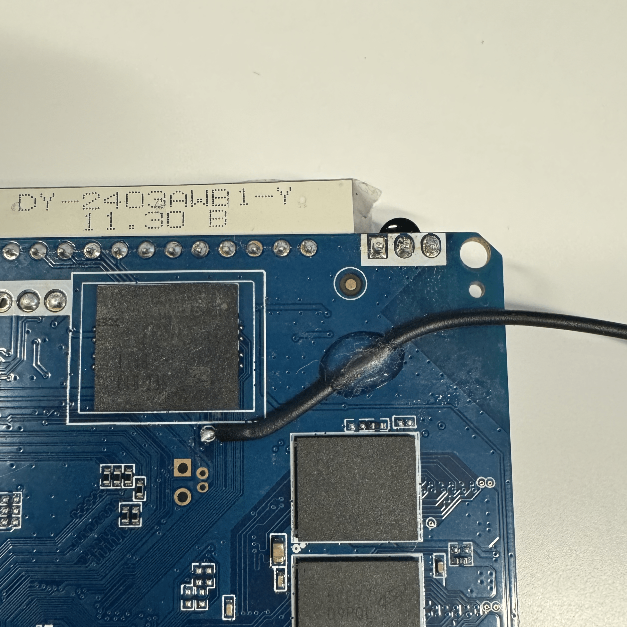
We started by finding the clock line, which was an exposed pad located by the LED display bar. We were able to manually short this line by pulling it to ground and force the boot process to crash.
We then began to go at it with the ChipWhisperer-Husky. We used a relay to connect power and wired the ChipWhisperer to it so we could control the reset. We hooked it up with a standard voltage glitching setup. We soldered on an SMA connector to the clock pad and attached the crowbar to that SMA connector. The problem with this is that by default the MOSFETs used by the ChipWhisperer were pulling the line to high. This stopped the device from booting at all and the ChipWhisperer was forcing a trigger. To fix this, we switched the setup and gave the device the standard clock glitching setup from the ChipWhisperer docs. This time we soldered a jumper wire to the clock pad and attached it to the hs2 line. This allowed us to run in high impedance mode and then ground the line on an appropriate trigger. We did not find success with this, but we did make it crash a few times. It is plausible that we could successfully glitch the box but decided to move on to JTAG as it seemed more promising.
Extraction Attempt: Using U-Boot
While messing around, we found a way to access U-Boot. We connected via ADB and ran the adb reboot bootloader command. This booted us into fastboot. We will talk more about fastboot later, but for now, while booted into fastboot we were able to go back to the UART serial console hold CTRL + C, and enter U-Boot. After looking through the commands, we couldn’t find ums so we couldn’t just mount the box and extract all the flash. We tried writing a simple Depthcharge script that would extract all the flash through the U-Boot shell but it was extremely slow and would have taken days.
Doing some more digging into the commands, we found 2 important commands, setenv which lets you set an environment variable, and saveenv which would write it to flash. The first thing we did was update the boot delay so we could easily get into U-Boot again.
setenv bootdelay 20
saveenv
Looking through the environment variables using printenv, we found the init and bootargs variables which control how the kernel should initialize including what file the kernel should run to continue initialization. This includes setting up filesystems and mounting partitions so if we could change this, no partitions would be mounted and we could easily image it. Originally it pointed to /init so we tried to use setenv to update it to point to sh or bash. No matter what directory we tried to find the binaries in(/, /bin/, /system/bin/), the kernel could not find the file and would default to the original init script.
After learning a little about how the kernel starts, we realized that it initially loads an initramfs. An initramfs is a file that gets extracted as the root filesystem that the kernel then tries to find the init script in. To look at the initramfs it was using currently, we took the boot partition (p3) and used the abootimg tool to extract the initramfs from the ramdisk.
abootimg -x <p3>This returns 3 files, bootimg.cfg which stores boot configurations, zImage the compressed Linux kernel, and initrd.img which is the initramfs(although it is named initrd it is an initramfs). To extract the filesystem, we first need to gunzip it and then read the cpio archive. In Ubuntu, simply renaming the file to initrd.gz and clicking extract here will automatically read the cpio archive and put it in a folder. Looking through the folder, we can see that the only binary is the init script. This means we will need to create our boot partition with a new initramfs if we want it to directly launch a shell.
We updated the folder by adding bash and busybox to a bin folder then created the new ramdisk by making a cpio archive and zipping it.
find . -print | cpio -o > ../ramdisk.cpio
cd ..
gzip -q -c ./ramdisk.cpio > ./ramdisk.gz
We then updated the boot partition by using abootimg. Note: This will edit the file you pass in so it is a good idea to have a copy of the original
abootimg -u <p3> -r ramdisk.gzWith our new boot partition, we now needed a way to put it on our device. We simply dd the contents onto the boot partition in Linux. This also meant that if it didn’t boot we would have a slight problem.
We booted the box hoping to be greeted by a shell but instead, U-Boot refused to boot the new partition because it failed to verify it. We now needed a way to flash the original partition back onto the box else it would just be a paperweight.
Luckily, we could use a great tool that we mentioned earlier, fastboot. Fastboot is a protocol that Android bootloaders use to communicate with computers. It allows you to flash partitions including the boot one. To enter it we got a U-Boot shell(luckily we set the boot delay beforehand) and then ran the fastboot command. Then we could connect the TV box to our computer and use the fastboot command on the computer which was already installed(it’s included in the Android SDK). With fastboot, we could flash the original boot partition.
fastboot flash boot p3-modifiedWe were close, we just needed a way to force U-Boot to boot our modified partition. This is where JTAG came in.
Extraction Attempt: JTAG
JTAG (Joint Test Action Group) is a standard for testing and debugging electronic circuits. It allows us to do hardware-level debugging, such as setting breakpoints, and modifying memory. It is controlled via a state machine. We will talk more about how the state machine works and how we implemented it later on in this writeup, but we recommend you read this writeup to learn more. To interact with JTAG, there are 4 important signals: TCK which is the clock signal, TMS which controls moving through the state machine, TDO which is output from the device being tested, and TDI which is input to the device being tested.
We decided to use JTAG next to allow us to debug at the hardware level. This first required us to have a JTAG interface which we were able to find in the H616 user manual in section 9.6.3.1.
Here is some context to understand what the user manual is saying: * Register: A register is a small amount of high-speed memory (in this case 32 bits per register) in the CPU that is used to store various important things including, in our case, pin configurations, pin output, and pin input * Port: A port is a group of pins that are controlled by common registers and share the same design (outlined in Figure 9-32)
Looking at table 9-14, we noticed that the CPU was using certain pins for multiple purposes. This is called multiplexing and it is quite common as oftentimes there are not enough pins for all of the functions. Looking at JTAG, we can see it is being multiplexed with the SD card and the function of each pin is controlled by certain registers in port PF. Looking at section 9.6.4, we can see that the base address for all the ports is 0x300B000. We can then look at table 9.6.5.9 which has an offset 0xB4 and lists the values for the register PF_CFG0 which configures what functions the pins of port PF are used for. Combining the base and offset, we get the address 0x300B0B4 which is where the register we need to set lives. Looking at the specific bits in the table, we can see that we need to set bits 0:2, 4:6, 12:14, and 20:22 to 011 to have the pins work in JTAG mode.
We first used U-Boot to md the address and after looking at the bits, we noticed that it was already set up for JTAG. We then used an SD card breakout board to connect to the JTAG interface and start talking to it.
Attempt 1: Rasberry Pi 5 + OpenOCD
Originally we attempted to use the Raspberry Pi 5 and connect to the JTAG TAP using the Pi pinout, however, this did not work as we ran into problems configuring and controlling the GPIO pins. On older Raspberry Pi’s, there was a single file /dev/gpiomem which could be used to directly talk with registers that controlled the peripherals including setting the mode and state of the GPIO pins. However, in the Pi 5, the file was split into multiple /dev/gpiomem<num> files which control different registers. This caused issues as the memory offsets that openOCD tried to use to control the GPIO would either freeze the pi (such as when <num> was 1,2,3 or 4) or cause openOCD to error.
Attempt 2: Raspberry Pi Pico
We then tried to use a Raspberry Pi pico along with the pico dirtyJTAG project. At first, we tried to compile the program manually but ran into some missing header file errors so we just used the precompiled release files. Flashing the pico was easy. We just plugged it into a computer while holding the boot button and it showed up as a storage device that you could drag a .uf2 file into. After flashing it, it successfully showed up as the right USB device but support for openOCD seemed to be in progress and there was an open patch review so we decided to try a different method.
Attempt 3: Raspberry Pi 4
Next, we attempted to use a Rasberry Pi 4 and OpenOCD, the thought behind this is that it will fix the problem we were having with GPIO mem. From there we built out a depthcharge script that allowed us to do the memory mapping automatically. From there we built OpenOCD and began writing a config file so that we were able to interact with it, we got very close, but it never completely worked. After more googling, we decided to pivot and attempt to use the JLINK.
Attempt 4: Ubuntu Laptop + JLINK
Finally, we found success using a JLINK. Setting up and using the software was relatively straightforward after following their docs. We used the JLinkGDBServerExe to start a GDB server. After setting all of the parameters through the GUI, we got the command JLinkGDBServerExe -select USB -device Cortex-A53 -endian little -if JTAG -speed auto -noir -noLocalhostOnly -nologtofile -port 2331 -SWOPort 2332 -TelenetPort 2333 which we could run to start a pre-configured GDB server.
We then connected to the server through GDB using target remote-extended :2331 and set the architecture using set architecture arm.
With JTAG working, we now needed to load U-Boot into Ghidra so we could properly analyze what it was doing. After loading the code into Ghidra, we needed to set the base address to 0x4a000000(we got the address from the boot log from uboot entry). With that and using the arm v8 architecture, we were able to successfully decompile U-Boot and could now find where it was doing the boot verification.
Unfortunately, we were not able to set breakpoints, as it would crash the box and JTAG. After a little investigation, we realized that U-Boot was relocating itself from the original address(0x4a000000) so our breakpoints were at random places. We were able to find the true offset of U-Boot by finding the address where U-Boot is idle and waiting for a command to be entered which was at 0xbfefae7e. A few bytes at that address were c0 b2 bf f3. Then we went to Ghidra and found the same bytes at 0x4a03be7e. We then wrote a simple Python function to convert our address.
correct_addr = lambda addr : hex(addr + 0xbfefae7e - 0x4a03be7e)When booting, we were running into an error that said that our image’s length did not match. We went to Ghidra and found the string image_len not match, actual:%d, expected:%lld\n" The string has one x-ref to a function we call func_image_len(). To skip the checks in the image_len function we found the if statement that compares the length located at 0x4a004af8
if (*(int *)(iVar1 + 0x14) != 0 || param_3 != *(int *)(iVar1 + 0x10)) {
printf(3,PTR_s_image_len_not_match,_actual:%d,_e_4a004ce0,param_3,iVar2,
 *(int *)(iVar1 + 0x10),*(int *)(iVar1 + 0x14));
goto LAB_4a004b4a;
}
To always pass the test, we converted the beq to a b instruction by replacing the memory at 0xbfec3bf8 with 0x07e0.
It worked! We skipped the image length checker but now had a similar problem where the hashes were not matching. We can bypass this check in a similar way. We find the if statement of where the check takes place:
iVar1 = FUN_4a066c8c(iVar7,auStack_100,0x20);
if (iVar1 == 0) {
 return 0;
}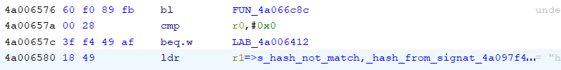
To bypass this, we again converted the beq.w instruction to a b.w by replacing the memory at 0xbfec3ca6 with FFF741BF.
This also works as we bypass the hash check, however, now we run into a CACHE: Misalignment error. This will prove to be more challenging as we can not just skip the check (we tried). We will have to fix the alignment of p3 for the bootloader to run correctly. What is interesting is that we checked the memory at 0x45000000 which is within the array of the misaligned cache, and it is a correctly aligned Android boot image.
After a little more investigation, we realized that we set GDB to default to arm so when it encountered thumb instructions at a breakpoint, it would freak out. After setting the fallback mode set arm fallback-mode thumb, we were able to set breakpoints. We also realized that the CACHE error was present even when booting the real image so the issue had to be with how we bypassed the checks mentioned above.
We dug around a little and found that the function that checked image length and hash returned at 0xbfec3b2c. Now that we could set breakpoints, we set a breakpoint after it performed the validation and let it validate the original boot image. Then when the breakpoint was hit, we would overwrite the original image that U-Boot loaded at 0x45000000 with a modified one that had a few bytes changed and U-Boot happily executed it thinking it was the original one.
Now that we could load a custom image, we just needed to make one that had the tools needed to allow us to extract all the partitions. We quickly wrote a script (you can find it here) that would create a new boot image with a custom ramdisk and the original kernel and boot config. We excitedly loaded the custom boot image and… It didn’t work. After some investigation, we found out that it expected a specific cpio archive format to extract correctly so we updated the command to use cpio --null --create --verbose --format=newc and put a small test C program that just prints hello world repeatedly. After waiting forever for the partition to flash again (because we had to flash it through JTAG and GDB, it took multiple minutes), it booted and printed hello world!
Now that we had control over the init process, we created another boot image with busybox and bash from here and updated our C program to call system("/bin/busybox sh"). After uploading and running it, we were met with a kernel panic Kernel panic - not syncing: Attempted to kill init! exitcode=0x00000000. We had a print statement at the top of our script that got called so we knew that it was running init but it never spawned a shell even when we tried to use bash. At first, we thought this was due to the kernel not being set up correctly and bash requiring some file or environment variable that was not yet initialized. But after looking at the man page for system, we realized that it called execl with /bin/sh which was not in our binary. Once we updated our init script to use execve to call busybox, we were finally able to get a shell.
Now that we have a shell, we should just be able to dd the partitions into a USB stick and be done right? Well not quite, the original init script sets up a lot of things including the proc filesystem, sysfs, and udevd which abstract away and give nice file paths to many devices and kernel objects. To use the dd command, we need a file path for both the MMC flash device (usually /dev/mmcblk0) and the USB device. To make the path for the MMC block device, we needed to use the command mknode which requires and major and minor number for identification. To find these numbers, we needed access to the proc filesystem which we could mount with the command mount -t proc proc /proc. Once it was mounted, we were able to look under /proc/devices to find the major number for the MMC device listed under Block Devices:. With that, we were able to mount block 0 using mknod /dev/mmcblk0 b <num> 0. With the MMC mounted, we just needed a USB stick that we could transfer all the data to. At first, we looked in the same device file to see if we could find the major number for the USB stick but there weren’t any obvious entries that corresponded with the drive. After some googling, we figured out we needed to mount the sysfs with mount -t sysfs sysfs /sys to find the major and minor numbers. each USB storage device gets a SCSI number which can be found in /proc/scsi/usb-storage (for us it was 0, likely because that was the only USB storage device). With this number you can look at the file /sys/class/scsi_disk/<num>:<num>:<num>:<num>/device/block/sda/<partition>/dev to get the major and minor number for a specific partition. With this, we made a node with mknod /dev/USB<num> b <major> <minor>. We then mounted the node with mount /dev/USB<num> /mnt/usb as it had a filesystem and other data on it and then finally used dd if=/dev/mmcblk0 of=/mnt/usb/flash.bin to copy the MMC onto the USB drive.
Conclusion
In this post, we created an automated Depthcharge script to produce consistent logs and dump the flash on 4 of the STBs. We then live imaged the 8K618-T and used JTAG to make a custom ramdisk to extract the flash from the T95. In our next blog, we will analyze the filesystems we dumped to look for indicators of compromise(IoCs) and vulnerabilities.